- 您现在的位置:买卖IC网 > PDF目录17010 > MAX117EVKIT-DIP (Maxim Integrated Products)EVAL KIT FOR MAX117 PDF资料下载
参数资料
| 型号: | MAX117EVKIT-DIP |
| 厂商: | Maxim Integrated Products |
| 文件页数: | 2/12页 |
| 文件大小: | 0K |
| 描述: | EVAL KIT FOR MAX117 |
| 产品培训模块: | Lead (SnPb) Finish for COTS Obsolescence Mitigation Program |
| 标准包装: | 1 |
| ADC 的数量: | 1 |
| 位数: | 8 |
| 采样率(每秒): | 400k |
| 数据接口: | 并联 |
| 输入范围: | ±VREF |
| 在以下条件下的电源(标准): | 4.5mW @ 400kSPS |
| 工作温度: | 0°C ~ 70°C |
| 已用 IC / 零件: | MAX117,MAX118 |
| 已供物品: | 板,CD |
MAX113/MAX117
Initial Power-Up
When power is first applied, perform a conversion to
initialize the MAX113/MAX117. Disregard the output
data.
Bypassing
Use a 4.7F electrolytic in parallel with a 0.1F ceramic
capacitor to bypass VDD to GND. Minimize capacitor
lead lengths.
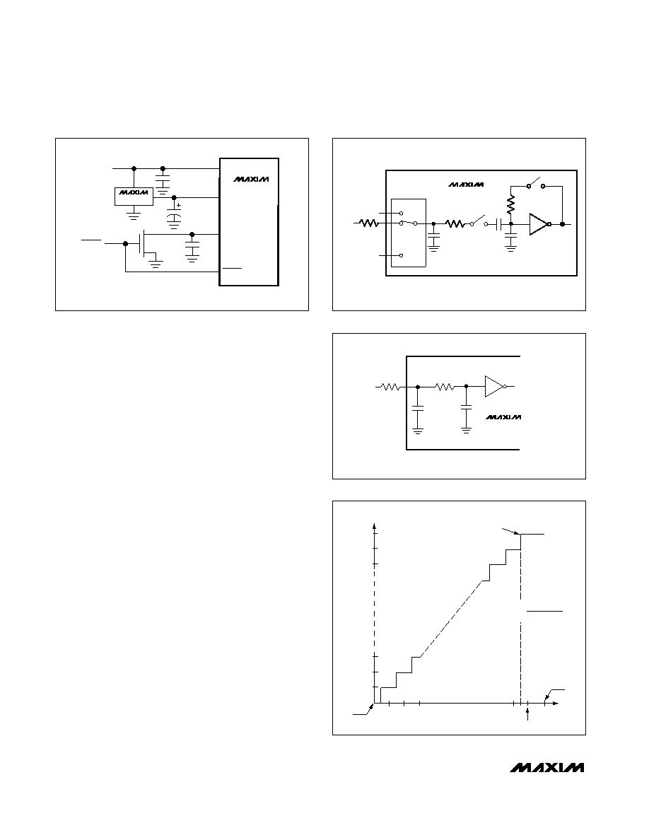
Bypass the reference inputs with 0.1F capacitors, as
shown in Figures 7a, 7b, and 7c.
Analog Inputs
Figure 8 shows the equivalent circuit of the MAX113/
MAX117 input. When a conversion starts and
WR is
low, VIN_ is connected to sixteen 0.6pF capacitors.
During this acquisition phase, the input capacitors
charge to the input voltage through the resistance of
the internal analog switches. In addition, about 22pF of
stray capacitance must be charged. The input can be
modeled as an equivalent RC network (Figure 9). As
source impedance increases, the capacitors take
longer to charge.
The typical 32pF input capacitance allows source resis-
tance as high as 1.5k
without setup problems. For
larger resistances, the acquisition time (tACQ) must be
increased.
Internal protection diodes, which clamp the analog
input to VDD and GND, allow the channel input pins to
swing from GND - 0.3V to VDD + 0.3V without damage.
However, for accurate conversions near full scale and
zero scale the inputs must not exceed VDD by more
than 50mV or be lower than GND by 50mV.
+3V, 400ksps, 4/8-Channel,
8-Bit ADCs with 1A Power-Down
10
______________________________________________________________________________________
RON
RIN
VIN2
MAX113
MAX117
.
T/H
MUX
2k
R
VIN_
1
22pF
VIN
MAX113
MAX117
10pF
Figure 8. Equivalent Input Circuit
Figure 9. RC Network Equivalent Input Model
REF-
MAX113
MAX117
VDD
MAX872
REF+
+3V
0.1F
C1
4.7F
PWRDN
N-FET*
* IRML2402
0.1F
Figure 7d. An N-channel MOSFET switches off the reference
load during power-down
OUTPUT CODE
INPUT VOLTAGE (LSBs)
FS
FS - 1LSB
FULL-SCALE
TRANSITION
12
3
11111111
11111110
11111101
00000011
00000010
00000001
00000000
1LSB =
VREF+ - VREF-
256
VREF-
VREF+
Figure 10. Transfer Function
相关PDF资料 |
PDF描述 |
|---|---|
| VE-B2Z-EW | CONVERTER MOD DC/DC 2V 40W |
| SDR1006-390KL | INDUCTOR POWER 39UH 1.35A SMD |
| PCM16XB1 | PROCESSOR MODULE FOR MPLAB-ICE |
| MAX110EVKIT-DIP | EVAL KIT FOR MAX110 |
| MAX11635EVKIT+ | KIT EVAL FOR 12-BIT ADCS 4-CH |
相关代理商/技术参数 |
参数描述 |
|---|---|
| MAX117MJI | 功能描述:模数转换器 - ADC RoHS:否 制造商:Texas Instruments 通道数量:2 结构:Sigma-Delta 转换速率:125 SPs to 8 KSPs 分辨率:24 bit 输入类型:Differential 信噪比:107 dB 接口类型:SPI 工作电源电压:1.7 V to 3.6 V, 2.7 V to 5.25 V 最大工作温度:+ 85 C 安装风格:SMD/SMT 封装 / 箱体:VQFN-32 |
| MAX11800ETC/V+ | 功能描述:触摸屏转换器和控制器 SPI 4Ch Touch Screen Controller RoHS:否 制造商:Microchip Technology 类型:Resistive Touch Controllers 输入类型:3 Key 数据速率:140 SPS 分辨率:10 bit 接口类型:4-Wire, 5-Wire, 8-Wire, I2C, SPI 电源电压:2.5 V to 5.25 V 电源电流:17 mA 工作温度:- 40 C to + 85 C 封装 / 箱体:SSOP-20 |
| MAX11800ETC/V+T | 功能描述:触摸屏转换器和控制器 SPI 4Ch Touch Screen Controller RoHS:否 制造商:Microchip Technology 类型:Resistive Touch Controllers 输入类型:3 Key 数据速率:140 SPS 分辨率:10 bit 接口类型:4-Wire, 5-Wire, 8-Wire, I2C, SPI 电源电压:2.5 V to 5.25 V 电源电流:17 mA 工作温度:- 40 C to + 85 C 封装 / 箱体:SSOP-20 |
| MAX11800ETC+ | 功能描述:触摸屏转换器和控制器 SPI 4Ch Touch Screen Controller RoHS:否 制造商:Microchip Technology 类型:Resistive Touch Controllers 输入类型:3 Key 数据速率:140 SPS 分辨率:10 bit 接口类型:4-Wire, 5-Wire, 8-Wire, I2C, SPI 电源电压:2.5 V to 5.25 V 电源电流:17 mA 工作温度:- 40 C to + 85 C 封装 / 箱体:SSOP-20 |
| MAX11800ETC+T | 功能描述:触摸屏转换器和控制器 SPI 4Ch Touch Screen Controller RoHS:否 制造商:Microchip Technology 类型:Resistive Touch Controllers 输入类型:3 Key 数据速率:140 SPS 分辨率:10 bit 接口类型:4-Wire, 5-Wire, 8-Wire, I2C, SPI 电源电压:2.5 V to 5.25 V 电源电流:17 mA 工作温度:- 40 C to + 85 C 封装 / 箱体:SSOP-20 |
发布紧急采购,3分钟左右您将得到回复。