- 您现在的位置:买卖IC网 > PDF目录9707 > MAX11801ETC/V+ (Maxim Integrated Products)IC TOUCH SCREEN CTRLR LP 12WQFN PDF资料下载
参数资料
| 型号: | MAX11801ETC/V+ |
| 厂商: | Maxim Integrated Products |
| 文件页数: | 37/59页 |
| 文件大小: | 0K |
| 描述: | IC TOUCH SCREEN CTRLR LP 12WQFN |
| 其它有关文件: | Automotive Product Guide |
| 产品培训模块: | Lead (SnPb) Finish for COTS Obsolescence Mitigation Program |
| 标准包装: | 75 |
| 类型: | 电阻 |
| 触摸面板接口: | 4 线 |
| 输入数/键: | 1 TSC |
| 分辨率(位): | 12 b |
| 评估套件: | 可供 |
| 数据接口: | I²C,串行 |
| 数据速率/采样率 (SPS,BPS): | 105k |
| 电源电压: | 1.7 V ~ 3.6 V |
| 工作温度: | -40°C ~ 85°C |
| 安装类型: | 表面贴装 |
| 封装/外壳: | 12-WQFN 裸露焊盘 |
| 供应商设备封装: | 12-TQFN-EP(4x4) |
| 包装: | 管件 |
第1页第2页第3页第4页第5页第6页第7页第8页第9页第10页第11页第12页第13页第14页第15页第16页第17页第18页第19页第20页第21页第22页第23页第24页第25页第26页第27页第28页第29页第30页第31页第32页第33页第34页第35页第36页当前第37页第38页第39页第40页第41页第42页第43页第44页第45页第46页第47页第48页第49页第50页第51页第52页第53页第54页第55页第56页第57页第58页第59页
MAX11800–MAX11803
master-generated 9th clock pulse if the previous byte is
successfully received. Monitoring ACK allows for detec-
tion of unsuccessful data transfers. An unsuccessful
data transfer occurs if a receiving device is busy or if a
system fault has occurred. In the event of an unsuc-
cessful data transfer, the bus master retries communica-
tion. The master pulls down SDA during the 9th clock
cycle to acknowledge receipt of data when the
MAX11801/MAX11803 are in read mode. An acknowl-
edge is sent by the master after each read byte to allow
data transfer to continue. A not-acknowledge is sent
when the master reads the final byte of data from the
MAX11801/MAX11803, followed by a STOP condition.
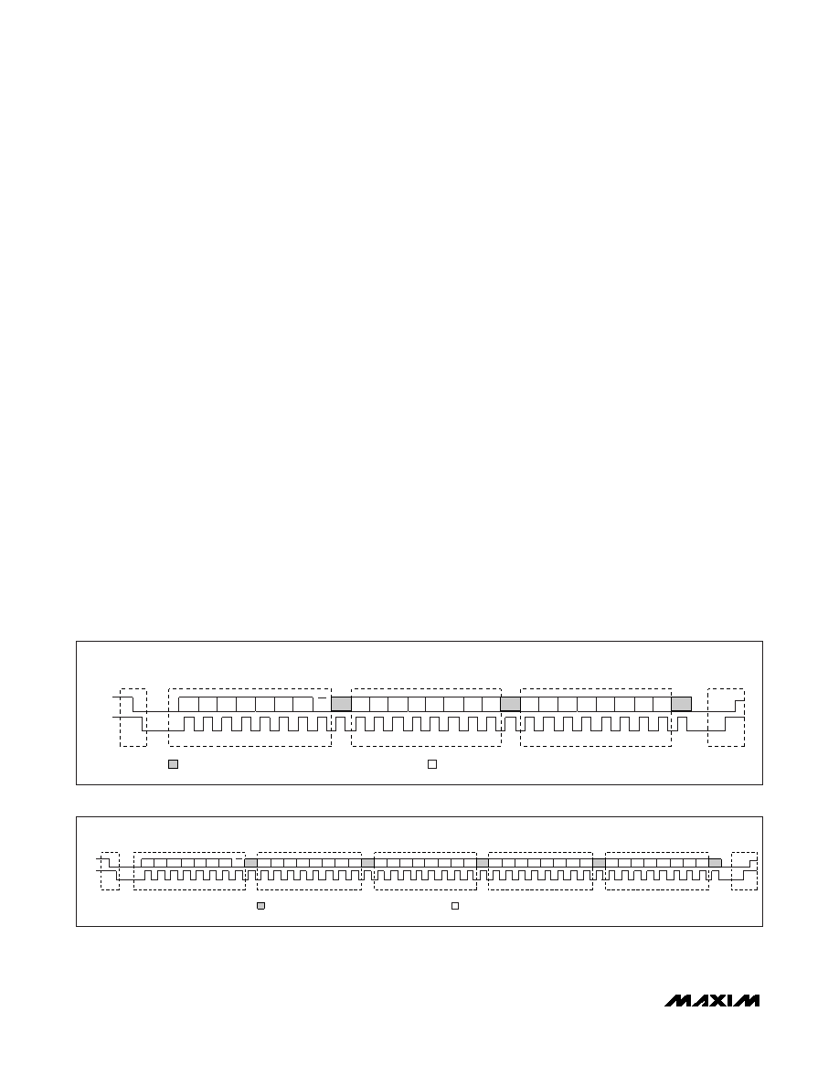
Write Data Format
A minimum write sequence to the MAX11801/
MAX11803 includes transmission of a START condition,
the slave address with the R/W bit set to 0, 1 byte of
data to select the internal register address pointer, 1
byte of data written to the selected register, and a
STOP condition. Figure 25 illustrates the proper frame
format for writing 1 byte of data to the MAX11801/
MAX11803. Figure 26 illustrates the frame format for
writing N-bytes of data to the MAX11801/MAX11803.
The slave address with the R/W bit set to 0 indicates
that the master intends to write data to the
MAX11801/MAX11803. The MAX11801/MAX11803
acknowledge receipt of the address byte during the
master-generated 9th SCL pulse.
The second byte transmitted from the master config-
ures the MAX11801/MAX11803’s internal register
address pointer. The pointer tells the MAX11801/
MAX11803 where to write the next byte of data. Note
that the MAX11801/MAX11803 use a 7-bit register
pointer format, and the selection should be left-justified
within the register byte (the last bit in the register byte is
a don’t care). An acknowledge pulse is sent by the
MAX11801/MAX11803 upon receipt of the address
pointer data.
The third byte sent to the MAX11801/MAX11803 contains
the data that is written to the chosen register. An
acknowledge pulse from the MAX11801/MAX11803 sig-
nals receipt of the data byte. The MAX11801/
MAX11803 do not support autoincrement in write
mode. However, by repeating multiple register address
byte + data byte pairs (bytes 2 and 3 in Figure 25) the
user can perform multiple register writes within a single
transfer. There is no limit as to how many registers
the user can write with a single command sequence,
but only commands listed as “pairable” can be
sequenced in this manner. For example, the I2C master
can perform multiple register writes to set up all required
conversion options and then issue a separate I2C com-
mand to start a conversion process. Figure 26 illustrates
how to write to multiple registers with one frame. The
master signals the end of transmission by issuing a
STOP condition. Register addresses greater than 0x0B
are reserved. Do not write to these addresses.
Low-Power, Ultra-Small Resistive Touch-Screen
Controllers with I2C/SPI Interface
42
______________________________________________________________________________________
START
WRITE ADDRESS
BYTE 1: DEVICE ADDRESS
WRITE REGISTER NUMBER
BYTE 2: REG NUMBER = N
WRITE DATA
BYTE 3: REG(N)[7:0] DATA
STOP
W
N3 N2 N1 N0
X
D
N4
1
0
1
0
A1 A0
N5
N6
Z
X
D
Z
WRITE DATA
BYTE 5: REG(Z)[7:0] DATA
WRITE REGISTER NUMBER
BYTE 4: REG NUMBER = Z
SDA
SCL
A
AA
A
ACKNOWLEDGE GENERATED BY I2C MASTER
ACKNOWLEDGE GENERATED BY MAX11801/MAX11803
Figure 26. I2C Multiple Write Sequence
SCL
W
N3 N2 N1 N0
X
D
START
SDA
WRITE ADDRESS
BYTE 1: DEVICE ADDRESS
WRITE REGISTER NUMBER
BYTE 2: FIRST REG NUMBER = N
WRITE DATA
BYTE 3: REG(N)[7:0] DATA
STOP
N4
1
0
1
0
A1
A0
N5
N6
AA
A
ACKNOWLEDGE GENERATED BY I2C MASTER
ACKNOWLEDGE GENERATED BY MAX11801/MAX11803
Figure 25. I2C Single Write Sequence
相关PDF资料 |
PDF描述 |
|---|---|
| V24B24M150B | CONVERTER MOD DC/DC 24V 150W |
| M83723/86R1002N | CONN PLUG 2POS STRAIGHT W/SCKT |
| V24B15M150BL3 | CONVERTER MOD DC/DC 15V 150W |
| M83723/75R1415N | CONN PLUG 15POS STRAIGHT W/SCKT |
| MS27473E14F35PD | CONN PLUG 37POS STRAIGHT W/PINS |
相关代理商/技术参数 |
参数描述 |
|---|---|
| MAX11801EVKIT+ | 功能描述:数据转换 IC 开发工具 MAX11801 Eval Kit RoHS:否 制造商:Texas Instruments 产品:Demonstration Kits 类型:ADC 工具用于评估:ADS130E08 接口类型:SPI 工作电源电压:- 6 V to + 6 V |
| MAX11801EWC+ | 制造商:Maxim Integrated Products 功能描述: |
| MAX11801EWC+T | 功能描述:触摸屏转换器和控制器 I2C 4Ch Touch Screen Controller RoHS:否 制造商:Microchip Technology 类型:Resistive Touch Controllers 输入类型:3 Key 数据速率:140 SPS 分辨率:10 bit 接口类型:4-Wire, 5-Wire, 8-Wire, I2C, SPI 电源电压:2.5 V to 5.25 V 电源电流:17 mA 工作温度:- 40 C to + 85 C 封装 / 箱体:SSOP-20 |
| MAX11801GTC/V+ | 功能描述:触摸屏转换器和控制器 I2C 4Ch Touch Screen Controller RoHS:否 制造商:Microchip Technology 类型:Resistive Touch Controllers 输入类型:3 Key 数据速率:140 SPS 分辨率:10 bit 接口类型:4-Wire, 5-Wire, 8-Wire, I2C, SPI 电源电压:2.5 V to 5.25 V 电源电流:17 mA 工作温度:- 40 C to + 85 C 封装 / 箱体:SSOP-20 |
| MAX11801GTC/V+T | 功能描述:触摸屏转换器和控制器 I2C 4Ch Touch Screen Controller RoHS:否 制造商:Microchip Technology 类型:Resistive Touch Controllers 输入类型:3 Key 数据速率:140 SPS 分辨率:10 bit 接口类型:4-Wire, 5-Wire, 8-Wire, I2C, SPI 电源电压:2.5 V to 5.25 V 电源电流:17 mA 工作温度:- 40 C to + 85 C 封装 / 箱体:SSOP-20 |
发布紧急采购,3分钟左右您将得到回复。