- 您现在的位置:买卖IC网 > PDF目录1935 > MAX1221BETX+T (Maxim Integrated Products)IC ADC/DAC 12BIT W/FIFO 36TQFNEP PDF资料下载
参数资料
| 型号: | MAX1221BETX+T |
| 厂商: | Maxim Integrated Products |
| 文件页数: | 15/44页 |
| 文件大小: | 0K |
| 描述: | IC ADC/DAC 12BIT W/FIFO 36TQFNEP |
| 产品培训模块: | Lead (SnPb) Finish for COTS Obsolescence Mitigation Program |
| 标准包装: | 2,500 |
| 类型: | ADC,DAC |
| 分辨率(位): | 12 b |
| 采样率(每秒): | 225k |
| 数据接口: | MICROWIRE?,QSPI?,串行,SPI? |
| 电压电源: | 模拟和数字 |
| 电源电压: | 2.7 V ~ 5.25 V |
| 工作温度: | -40°C ~ 85°C |
| 安装类型: | 表面贴装 |
| 封装/外壳: | 36-WFQFN 裸露焊盘 |
| 供应商设备封装: | 36-TQFN 裸露焊盘(6x6) |
| 包装: | 带卷 (TR) |
第1页第2页第3页第4页第5页第6页第7页第8页第9页第10页第11页第12页第13页第14页当前第15页第16页第17页第18页第19页第20页第21页第22页第23页第24页第25页第26页第27页第28页第29页第30页第31页第32页第33页第34页第35页第36页第37页第38页第39页第40页第41页第42页第43页第44页
MAX1221/MAX1223/MAX1343
12-Bit, Multichannel ADCs/DACs with FIFO,
Temperature Sensing, and GPIO Ports
22
______________________________________________________________________________________
LSB per degree. See the
Temperature Measurements
section for details on converting the digital code to a tem-
perature.
12-Bit DAC
In addition to the 12-bit ADC, the MAX1221/MAX1223/
MAX1343 also include eight (MAX1221/MAX1223) or
four (MAX1343) voltage-output, 12-bit, monotonic DACs
with less than 4 LSB integral nonlinearity error and less
than 1 LSB differential nonlinearity error. Each DAC has
a 2s settling time and ultra-low glitch energy (4nVs).
The 12-bit DAC code is unipolar binary with 1 LSB =
VREF / 4096.
DAC Digital Interface
Figure 1 shows the functional diagram of the MAX1221.
The shift register converts a serial 16-bit word to parallel
data for each input register operating with a clock rate
up to 25MHz. The SPI-compatible digital interface to the
shift register consists of
CS, SCLK, DIN, and DOUT.
Serial data at DIN is loaded on the falling edge of SCLK.
Pull
CS low to begin a write sequence. Begin a write to
the DAC by writing 0001XXXX as a command byte. The
last 4 bits of the DAC select register are don’t-care bits.
See Table 10. Write another 2 bytes to the DAC inter-
face register following the command byte to select the
appropriate DAC and the data to be written to it. See
Tables 17 and 18.
The double-buffered DACs include an input and a DAC
register. The input registers are directly connected to the
shift register and hold the result of the most recent write
operation. The 12-bit DAC registers hold the current out-
put code for the respective DAC. Data can be transferred
from the input registers to the DAC registers by pulling
LDAC low or by writing the appropriate DAC command
sequence at DIN. See Table 17. The outputs of the DACs
are buffered through eight (MAX1221/MAX1223) or four
(MAX1343) rail-to-rail op amps.
The MAX1221/MAX1223/MAX1343 DAC output-voltage
range is based on the internal reference or an external
reference. Write to the setup register (see Table 5) to
program the reference. If using an external voltage
reference, bypass REF1 with a 0.1F capacitor to
AGND. The internal reference is 2.5V. When using an
external reference on any of these devices, the voltage
range is 0.7V to AVDD.
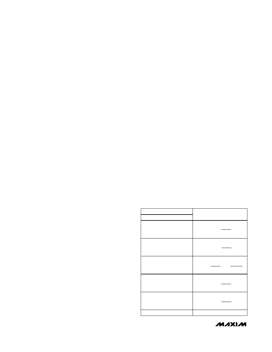
DAC Transfer Function
See Table 2 for various analog outputs from the DAC.
DAC Power-On Wake-Up Modes
The state of the RES_SEL input determines the wake-up
state of the DAC outputs. Connect RES_SEL to AVDD or
AGND upon power-up to be sure the DAC outputs
wake up to a known state. Connect RES_SEL to AGND
to wake up all DAC outputs at 000h. While RES_SEL is
low, the 100kΩ internal resistor pulls the DAC outputs to
AGND and the output buffers are powered down.
Connect RES_SEL to AVDD to wake up all DAC outputs
at FFFh. While RES_SEL is high, the 100kΩ pullup
resistor pulls the DAC outputs to VREF1 and the output
buffers are powered down.
DAC Power-Up Modes
See Table 18 for a description of the DAC power-up
and power-down modes.
GPIOs
In addition to the internal ADC and DAC, the
MAX1221/MAX1343 also provide four GPIO channels,
GPIOA0, GPIOA1, GPIOC0, GPIOC1. Read and write to
the GPIOs as detailed in Table 1 and Tables 12–16. Also,
see the
GPIO Command section. See Figures 11 and 12
for GPIO timing.
Write to the GPIOs by writing a command byte to the
GPIO command register. Write a single data byte to the
MAX1221/MAX1343 following the command byte.
The GPIOs can sink and source current. GPIOA0 and
GPIOA1 can sink and source up to 15mA. GPIOC0 and
GPIOC1 can sink 4mA and source 2mA. See Table 3.
DAC CONTENTS
MSB
LSB
ANALOG OUTPUT
1111
1000
0000
0001
1000
0000
0111
0000
0001
0000
0
+
VREF
4095
4096
+
= +
V
REF
2048
4096
2
+
VREF
2047
4096
+
VREF
1
4096
+
VREF
2049
4096
Table 2. DAC Output Code Table
相关PDF资料 |
PDF描述 |
|---|---|
| MAX1257BETM+T | IC ADC/DAC 12BIT 48-TQFN |
| MAX125CCAX+D | IC DAS 14BIT 2X4CH 36-SSOP |
| MAX1271AENG+ | IC ADC 12BIT 8CH 24-DIP |
| MAX127AENG+ | IC DAS 12BIT 2-WIRE 24-DIP |
| MAX13021ASA+ | IC TRANSCEIVER LIN 8-SOIC |
相关代理商/技术参数 |
参数描述 |
|---|---|
| MAX1223BETX | 制造商:Maxim Integrated Products 功能描述:12-BIT MULTICHANNEL ADC/DAC WITH F - Rail/Tube |
| MAX1223BETX+ | 制造商:Maxim Integrated Products 功能描述:12-BIT, MULTICHANNEL ADCS/DACS WITH FIFO, TEMPERATURE SENSIN - Rail/Tube 制造商:Maxim Integrated Products 功能描述:IC ADC 12BIT QFN 制造商:Maxim Integrated Products 功能描述:ADC / DAC Multichannel |
| MAX1223BETX+T | 制造商:Maxim Integrated Products 功能描述:12-BIT, MULTICHANNEL ADCS/DACS WITH FIFO, TEMPERATURE SENSIN - Tape and Reel 制造商:Maxim Integrated Products 功能描述:IC ADC 12BIT QFN |
| MAX1223BETX-T | 制造商:Maxim Integrated Products 功能描述:12-BIT MULTICHANNEL ADC/DAC WITH F - Tape and Reel |
| MAX1224ACTC | 制造商:Maxim Integrated Products 功能描述:1.5MSPS, SINGLE-SUPPLY, LOW-POWER, TRUE-DIFFE - Rail/Tube |
发布紧急采购,3分钟左右您将得到回复。