- 您现在的位置:买卖IC网 > PDF目录383314 > MAX1233EGI (MAXIM INTEGRATED PRODUCTS INC) 【15kV ESD-Protected Touch-Screen Controllers Include DAC and Keypad Controller PDF资料下载
参数资料
| 型号: | MAX1233EGI |
| 厂商: | MAXIM INTEGRATED PRODUCTS INC |
| 元件分类: | 消费家电 |
| 英文描述: | 【15kV ESD-Protected Touch-Screen Controllers Include DAC and Keypad Controller |
| 中文描述: | SPECIALTY CONSUMER CIRCUIT, QCC28 |
| 封装: | 5 X 5 MM, 0.80 MM HEIGHT, QFN-28 |
| 文件页数: | 15/44页 |
| 文件大小: | 706K |
| 代理商: | MAX1233EGI |
第1页第2页第3页第4页第5页第6页第7页第8页第9页第10页第11页第12页第13页第14页当前第15页第16页第17页第18页第19页第20页第21页第22页第23页第24页第25页第26页第27页第28页第29页第30页第31页第32页第33页第34页第35页第36页第37页第38页第39页第40页第41页第42页第43页第44页
M
±15kV ESD-Protected Touch-Screen
Controllers Include DAC and Keypad Controller
______________________________________________________________________________________
15
measurement of the auxiliary inputs.
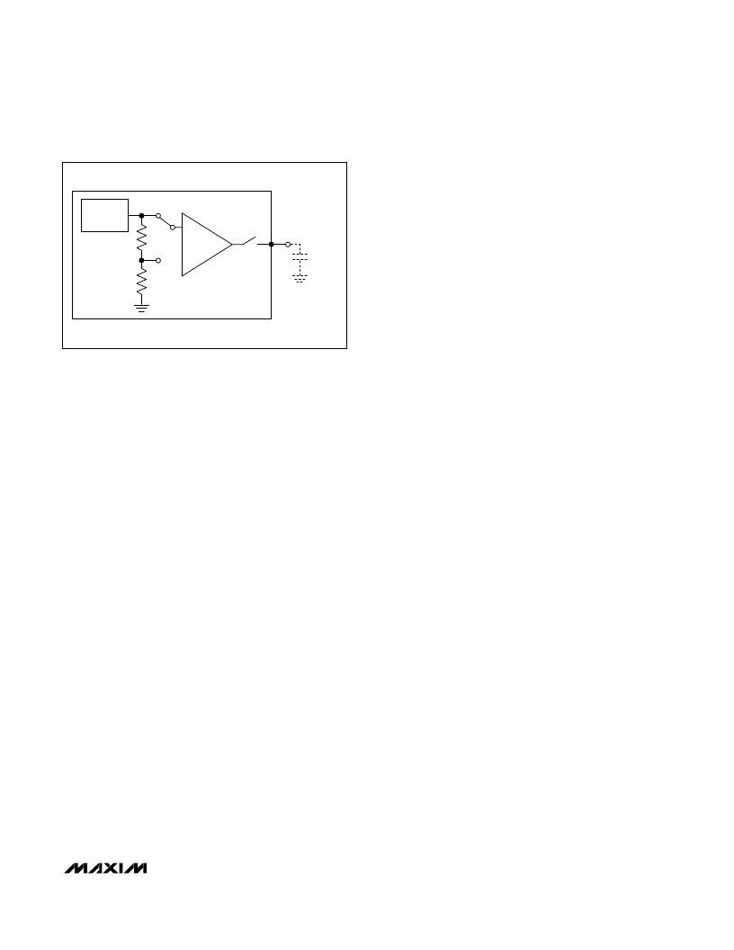
Figure 4
shows the
on-chip reference circuitry of the MAX1233/MAX1234.
Set the internal reference voltage by writing to the RFV
bits in the ADC control register (see
Tables
4, 5, and 12).
The MAX1233/MAX1234 can accept an external refer-
ence connected to REF for ADC conversion.
External Reference
The MAX1233/MAX1234 can accept an external refer-
ence connected to the REF pin for ADC conversions.
The internal reference should be disabled (RES1 = 1)
when using an external reference. At a conversion rate
of 50ksps, an external reference at REF must deliver up
to 15μA of load current and have 50
or less output
impedance. If the external reference has high output
impedance or is noisy, bypass it close to the REF pin
with a 0.1μF capacitor.
Selecting Internal or External Reference
Set the type of reference being used by programming
the ADC control register. To select the internal refer-
ence, clock zeros into bits [A/D3:A/D0] and a zero to bit
RES1, as shown in the
Control Registers
section. To
change to external reference mode, clock zeros into
bits [A/D3:A/D0] and a one to bit RES1. See
Table
1
3
for more information about selecting an internal or
external reference for the ADC.
Reference Power Modes
Auto Power-Down Mode (RES1 = RES0 = 0)
The MAX1233/MAX1234 are in auto power-down mode
at initial power-up. Set the RES1 and RES0 bits to zero
to use the MAX1233/MAX1234 in the auto power-down
mode. In this mode, the internal reference is normally
off. When a command to perform a battery measure-
ment, temperature measurement, or auxiliary input
measurement is written to the ADC control register, the
device powers on the internal reference, waits for the
internal reference to settle, completes the requested
scan, and powers down the internal reference. The ref-
erence power delay depends upon the ADC resolution
selected (see
Table 8
). Do not bypass REF with an
external capacitor when performing scans in auto
power-down mode.
Full-Power Mode (RES1 = 0, RES0 = 1)
In the full-power mode, the RES1 bit is set LOW and
RES0 bit is set HIGH. In this mode, the device is pow-
ered up and the internal ADC reference is always ON.
The MAX1233/MAX1234 internal reference remains fully
powered after completing a scan.
Internal Clock
The MAX1233/MAX1234 operate from an internal oscil-
lator, which is accurate to within 20% of the 10MHz
specified clock rate. The internal oscillator controls the
timing of the acquisition, conversion, touch-screen set-
tling, reference power-up, and keypad debounce times.
8-Bit DAC
The MAX1233/MAX1234 have a voltage-output, true 8-bit
monotonic DAC with less than 1LSB integral nonlinearity
error and less than 1LSB differential nonlinearity error. It
requires a supply current of only 150μA (typ) and pro-
vides a buffered voltage output. The DAC is at midscale
code at power-up and remains there until a new code is
written to the DAC register. During shutdown, the DAC
’
s
output is pulled to ground with a 1M
load.
The internal DAC can be used in various system applica-
tions such as LCD/TFT-bias control, automatic tuning
(VCO), power amplifier bias control, programmable
threshold levels, and automatic gain control (AGC).
The 8-bit DAC in the MAX1233/MAX1234 employs a
current-steering topology as shown in
Figure 5
. At the
core of this DAC is a reference voltage-to-current con-
verter (V/I) that generates a reference current. This cur-
rent is mirrored to 255 equally weighted current
sources. DAC switches control the outputs of these cur-
rent mirrors so that only the desired fraction of the total
current-mirror currents is steered to the DAC output.
The current is then converted to a voltage across a
resistor, and the output amplifier buffers this voltage.
DAC Output Voltage
The 8-bit DAC code is binary unipolar with 1LSB =
(V
REF
/256). The DAC has a full-scale output voltage of
(0.9
×
AV
DD
- 1LSB).
+1.25V
BANDGAP
2x
REF PIN
OPTIONAL
3R
2R
Figure 4. Block Diagram of the Internal Reference
相关PDF资料 |
PDF描述 |
|---|---|
| MAX1234EGI | 【15kV ESD-Protected Touch-Screen Controllers Include DAC and Keypad Controller |
| MAX1239 | 2.7V to 3.6V and 4.5V to 5.5V, Low-Power, 4-/12-Channel, 2-Wire Serial, 12-Bit ADCs |
| MAX1239LEEE | 2.7V to 3.6V and 4.5V to 5.5V, Low-Power, 4-/12-Channel, 2-Wire Serial, 12-Bit ADCs |
| MAX1239MEEE | Circular Connector; No. of Contacts:128; Series:D38999; Body Material:Metal; Connecting Termination:Crimp; Connector Shell Size:25; Circular Contact Gender:Pin; Circular Shell Style:Wall Mount Receptacle; Insert Arrangement:25-35 |
| MAX1238LEEE | DIODE ZENER DUAL COMMON-CATHODE 300mW 10Vz 5mA-Izt 0.06 0.1uA-Ir 7.5 SOT-23 3K/REEL |
相关代理商/技术参数 |
参数描述 |
|---|---|
| MAX1233EGI+ | 制造商:Maxim Integrated Products 功能描述: |
| MAX1233EGI-T | 功能描述:触摸屏转换器和控制器 RoHS:否 制造商:Microchip Technology 类型:Resistive Touch Controllers 输入类型:3 Key 数据速率:140 SPS 分辨率:10 bit 接口类型:4-Wire, 5-Wire, 8-Wire, I2C, SPI 电源电压:2.5 V to 5.25 V 电源电流:17 mA 工作温度:- 40 C to + 85 C 封装 / 箱体:SSOP-20 |
| MAX1233ETI+ | 功能描述:触摸屏转换器和控制器 4Ch uWire QSPI/SPI Touch Interface RoHS:否 制造商:Microchip Technology 类型:Resistive Touch Controllers 输入类型:3 Key 数据速率:140 SPS 分辨率:10 bit 接口类型:4-Wire, 5-Wire, 8-Wire, I2C, SPI 电源电压:2.5 V to 5.25 V 电源电流:17 mA 工作温度:- 40 C to + 85 C 封装 / 箱体:SSOP-20 |
| MAX1233ETI+T | 功能描述:触摸屏转换器和控制器 4Ch uWire QSPI/SPI Touch Interface RoHS:否 制造商:Microchip Technology 类型:Resistive Touch Controllers 输入类型:3 Key 数据速率:140 SPS 分辨率:10 bit 接口类型:4-Wire, 5-Wire, 8-Wire, I2C, SPI 电源电压:2.5 V to 5.25 V 电源电流:17 mA 工作温度:- 40 C to + 85 C 封装 / 箱体:SSOP-20 |
| MAX1234EGI | 功能描述:触摸屏转换器和控制器 RoHS:否 制造商:Microchip Technology 类型:Resistive Touch Controllers 输入类型:3 Key 数据速率:140 SPS 分辨率:10 bit 接口类型:4-Wire, 5-Wire, 8-Wire, I2C, SPI 电源电压:2.5 V to 5.25 V 电源电流:17 mA 工作温度:- 40 C to + 85 C 封装 / 箱体:SSOP-20 |
发布紧急采购,3分钟左右您将得到回复。