- 您现在的位置:买卖IC网 > PDF目录9893 > MAX1293ACEG+T (Maxim Integrated Products)IC ADC 12BIT 250KSPS 24-QSOP PDF资料下载
参数资料
| 型号: | MAX1293ACEG+T |
| 厂商: | Maxim Integrated Products |
| 文件页数: | 9/20页 |
| 文件大小: | 0K |
| 描述: | IC ADC 12BIT 250KSPS 24-QSOP |
| 产品培训模块: | Lead (SnPb) Finish for COTS Obsolescence Mitigation Program |
| 标准包装: | 2,500 |
| 位数: | 12 |
| 采样率(每秒): | 250k |
| 数据接口: | 并联 |
| 转换器数目: | 1 |
| 功率耗散(最大): | 762mW |
| 电压电源: | 单电源 |
| 工作温度: | 0°C ~ 70°C |
| 安装类型: | 表面贴装 |
| 封装/外壳: | 24-SSOP(0.154",3.90mm 宽) |
| 供应商设备封装: | 24-QSOP |
| 包装: | 带卷 (TR) |
| 输入数目和类型: | 4 个单端,单极;4 个单端,双极;2 个伪差分,单极;2 个伪差分,双极 |
MAX1291/MAX1293
250ksps, +3V, 8-/4-Channel, 12-Bit ADCs
with +2.5V Reference and Parallel Interface
______________________________________________________________________________________
17
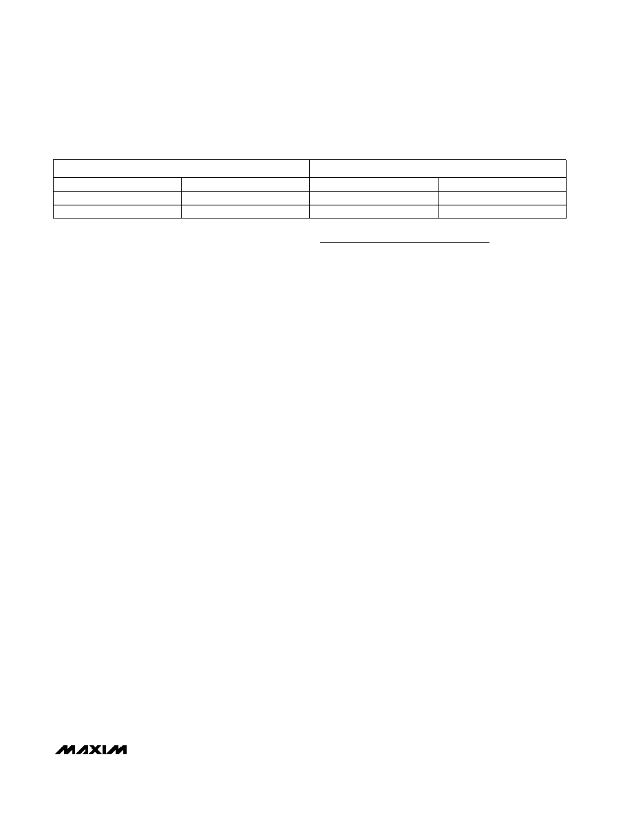
Table 6. Full-Scale and Zero-Scale for Unipolar and Bipolar Operation
UNIPOLAR MODE
BIPOLAR MODE
COM
Zero Scale
—
-VREF/2 + COM
Negative Full Scale
—
VREF + COM
VREF/2 + COM
Positive Full Scale
Full Scale
sion cycles, and 2 read cycles. This assumes that the
results of the last conversion are read before the next
control byte is written. Throughputs up to 300ksps can
be achieved by first writing a control word to begin the
acquisition cycle of the next conversion, and then read-
ing the results of the previous conversion from the bus
(Figure 10). This technique allows a conversion to be
completed every 16 clock cycles. Note that the switch-
ing of the data bus during acquisition or conversion
can cause additional supply noise, which can make it
difficult to achieve true 12-bit performance.
Layout, Grounding, and Bypassing
For best performance use printed circuit (PC) boards.
Wire-wrap configurations are not recommended since
the layout should ensure proper separation of analog
and digital traces. Do not run analog and digital lines
parallel to each other, and don’t lay out digital signal
paths underneath the ADC package. Use separate
analog and digital PC Board ground sections with only
one starpoint (Figure 11) connecting the two ground
systems (analog and digital). For lowest-noise opera-
tion, ensure the ground return to the star ground’s
power supply is low impedance and as short as possi-
ble. Route digital signals far away from sensitive analog
and reference inputs.
High-frequency noise in the power supply (VDD) could
influence the proper operation of the ADC’s fast com-
parator. Bypass VDD to the star ground with a network
of two parallel capacitors, 0.1F and 4.7F, located as
close as possible to the MAX1291/MAX1293s’ power
supply pin. Minimize capacitor lead length for best sup-
ply-noise rejection; add an attenuation resistor (5
) if
the power supply is extremely noisy.
Definitions
Integral Nonlinearity
Integral nonlinearity (INL) is the deviation of the values
on an actual transfer function from a straight line. This
straight line can be either a best-straight-line fit or a line
drawn between the endpoints of the transfer function,
once offset and gain errors have been nullified. The
static linearity parameters for the MAX1291/MAX1293
are measured using the endpoint method.
Differential Nonlinearity
Differential nonlinearity (DNL) is the difference between
an actual step width and the ideal value of 1 LSB. A
DNL error specification of less than 1 LSB guarantees
no missing codes and a monotonic transfer function.
Aperture Definitions
Aperture jitter (tAJ) is the sample-to-sample variation in
the time between the samples. Aperture delay (tAD) is
the time between the rising edge of the sampling clock
and the instant when an actual sample is taken.
Signal-to-Noise Ratio
For a waveform perfectly reconstructed from digital
samples, signal-to-noise ratio (SNR) is the ratio of the
full-scale analog input (RMS value) to the RMS quanti-
zation error (residual error). The ideal, theoretical mini-
mum analog-to-digital noise is caused by quantization
error only and results directly from the ADC’s resolution
(N bits):
SNR = (6.02 N + 1.76)dB
In reality, there are other noise sources besides quanti-
zation noise: thermal noise, reference noise, clock jitter,
etc. Therefore, SNR is computed by taking the ratio of
the RMS signal to the RMS noise which includes all
spectral components minus the fundamental, the first
five harmonics, and the DC offset.
Signal-to-Noise Plus Distortion
Signal-to-noise plus distortion (SINAD) is the ratio of the
fundamental input frequency’s RMS amplitude to the
RMS equivalent of all other ADC output signals.
SINAD (dB) = 20 log (SignalRMS / NoiseRMS)
相关PDF资料 |
PDF描述 |
|---|---|
| ISL32273EFVZ | IC RCVR RS485/422 QD ESD 16TSSOP |
| MAX184BCWG+T | IC ADC 12BIT HS 24-SOIC |
| ISL32179EFRZ | IC XMITTER ESD RS422 LP 24-QFN |
| MAX1264ACEG+T | IC ADC 12BIT 400KSPS 24-QSOP |
| IDT72T36115L6-7BB | IC FIFO 131KX36 6-7NS 240BGA |
相关代理商/技术参数 |
参数描述 |
|---|---|
| MAX1293AEEG | 功能描述:模数转换器 - ADC RoHS:否 制造商:Texas Instruments 通道数量:2 结构:Sigma-Delta 转换速率:125 SPs to 8 KSPs 分辨率:24 bit 输入类型:Differential 信噪比:107 dB 接口类型:SPI 工作电源电压:1.7 V to 3.6 V, 2.7 V to 5.25 V 最大工作温度:+ 85 C 安装风格:SMD/SMT 封装 / 箱体:VQFN-32 |
| MAX1293AEEG+ | 功能描述:模数转换器 - ADC 12-Bit 4Ch 250ksps 3.6V Precision ADC RoHS:否 制造商:Texas Instruments 通道数量:2 结构:Sigma-Delta 转换速率:125 SPs to 8 KSPs 分辨率:24 bit 输入类型:Differential 信噪比:107 dB 接口类型:SPI 工作电源电压:1.7 V to 3.6 V, 2.7 V to 5.25 V 最大工作温度:+ 85 C 安装风格:SMD/SMT 封装 / 箱体:VQFN-32 |
| MAX1293AEEG+T | 功能描述:模数转换器 - ADC 12-Bit 4Ch 250ksps 3.6V Precision ADC RoHS:否 制造商:Texas Instruments 通道数量:2 结构:Sigma-Delta 转换速率:125 SPs to 8 KSPs 分辨率:24 bit 输入类型:Differential 信噪比:107 dB 接口类型:SPI 工作电源电压:1.7 V to 3.6 V, 2.7 V to 5.25 V 最大工作温度:+ 85 C 安装风格:SMD/SMT 封装 / 箱体:VQFN-32 |
| MAX1293AEEG-T | 功能描述:模数转换器 - ADC RoHS:否 制造商:Texas Instruments 通道数量:2 结构:Sigma-Delta 转换速率:125 SPs to 8 KSPs 分辨率:24 bit 输入类型:Differential 信噪比:107 dB 接口类型:SPI 工作电源电压:1.7 V to 3.6 V, 2.7 V to 5.25 V 最大工作温度:+ 85 C 安装风格:SMD/SMT 封装 / 箱体:VQFN-32 |
| MAX1293BCEG | 功能描述:模数转换器 - ADC RoHS:否 制造商:Texas Instruments 通道数量:2 结构:Sigma-Delta 转换速率:125 SPs to 8 KSPs 分辨率:24 bit 输入类型:Differential 信噪比:107 dB 接口类型:SPI 工作电源电压:1.7 V to 3.6 V, 2.7 V to 5.25 V 最大工作温度:+ 85 C 安装风格:SMD/SMT 封装 / 箱体:VQFN-32 |
发布紧急采购,3分钟左右您将得到回复。