- 您现在的位置:买卖IC网 > PDF目录2008 > MAX1434ECQ+D (Maxim Integrated Products)IC ADC 10BIT 50MSPS 100-TQFP PDF资料下载
参数资料
| 型号: | MAX1434ECQ+D |
| 厂商: | Maxim Integrated Products |
| 文件页数: | 11/22页 |
| 文件大小: | 0K |
| 描述: | IC ADC 10BIT 50MSPS 100-TQFP |
| 标准包装: | 90 |
| 位数: | 10 |
| 采样率(每秒): | 50M |
| 数据接口: | LVDS,串行 |
| 转换器数目: | 8 |
| 功率耗散(最大): | 882mW |
| 电压电源: | 模拟和数字 |
| 工作温度: | -40°C ~ 85°C |
| 安装类型: | * |
| 封装/外壳: | 100-TQFP 裸露焊盘 |
| 供应商设备封装: | 100-TQFP(14x14) |
| 包装: | 托盘 |
| 输入数目和类型: | 8 个差分 |
Offset Error
Offset error is a figure of merit that indicates how well
the actual transfer function matches the ideal transfer
function at a single point. For the MAX1434, the ideal
midscale digital output transition occurs when there is -
1/2 LSBs across the analog inputs (Figures 6 and 7).
Bipolar offset error is the amount of deviation between
the measured midscale transition point and the ideal
midscale transition point.
Gain Error
Gain error is a figure of merit that indicates how well the
slope of the actual transfer function matches the slope
of the ideal transfer function. For the MAX1434, the gain
error is the difference of the measured full-scale and
zero-scale transition points minus the difference of the
ideal full-scale and zero-scale transition points.
For the bipolar devices (MAX1434), the full-scale transi-
tion point is from 0x1FE to 0x1FF for two’s-complement
output format (0x3FE to 0x3FF for offset binary) and the
zero-scale transition point is from 0x200 to 0x201 for
two’s complement (0x000 to 0x001 for offset binary).
Crosstalk
Crosstalk indicates how well each analog input is isolated
from the others. For the MAX1434, a 5.3MHz, -0.5dBFS
analog signal is applied to one channel while a 24.1MHz,
-0.5dBFS analog signal is applied to another channel. An
FFT is taken on the channel with the 5.3MHz analog sig-
nal. From this FFT, the crosstalk is measured as the dif-
ference in the 5.3MHz and 24.1MHz amplitudes.
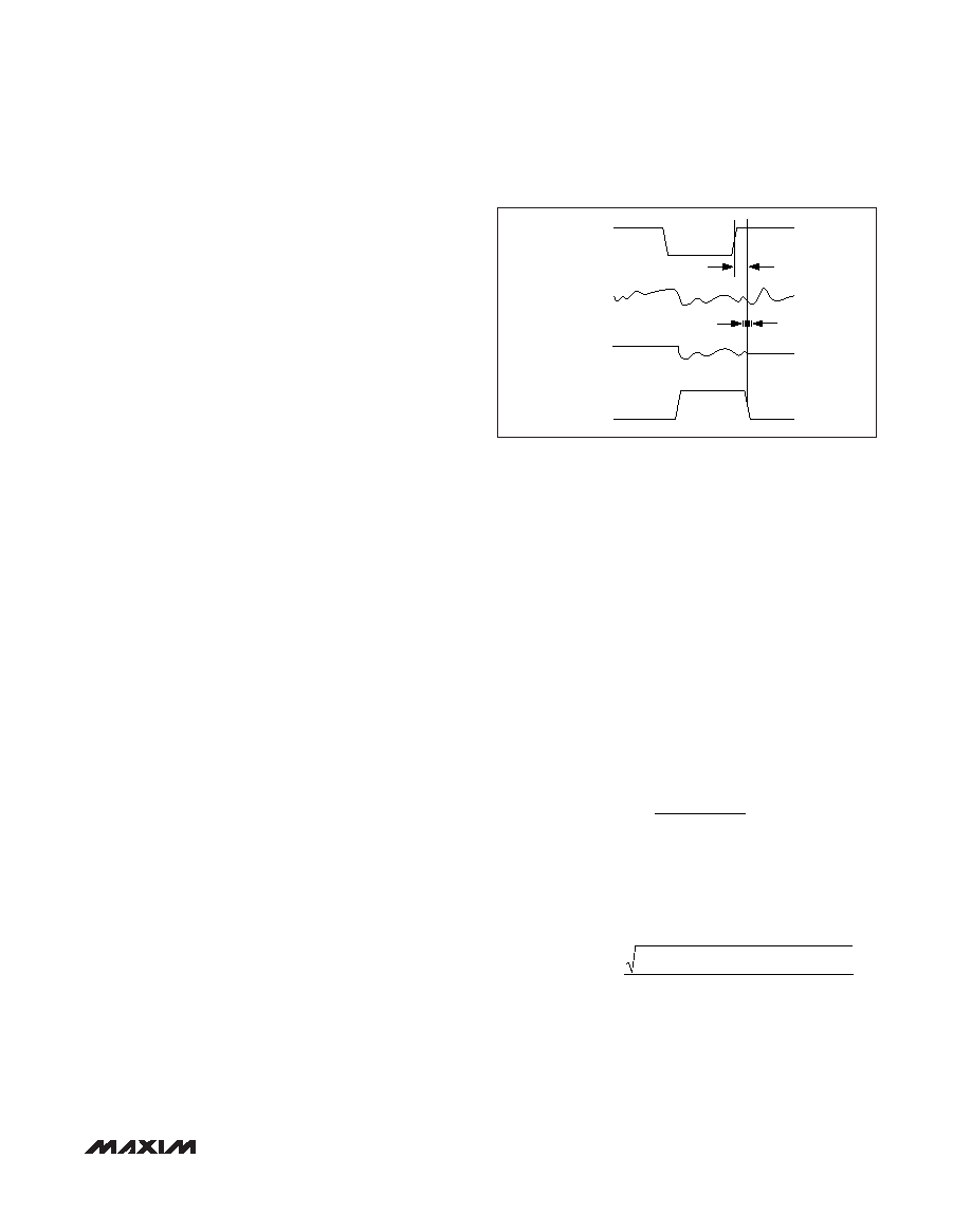
Aperture Delay
Aperture delay (tAD) is the time defined between the
rising edge of the sampling clock and the instant when
an actual sample is taken. See Figure 11.
Aperture Jitter
Aperture jitter (tAJ) is the sample-to-sample variation in
the aperture delay. See Figure 11.
Signal-to-Noise Ratio (SNR)
For a waveform perfectly reconstructed from digital
samples, the theoretical maximum SNR is the ratio of
the full-scale analog input (RMS value) to the RMS
quantization error (residual error). The ideal, theoretical
minimum analog-to-digital noise is caused by quantiza-
tion error only and results directly from the ADC’s reso-
lution (N bits):
SNRdB[max] = 6.02dB x N x 1.76dB
In reality, there are other noise sources besides quantiza-
tion noise: thermal noise, reference noise, clock jitter, etc.
For the MAX1434, SNR is computed by taking the ratio
of the RMS signal to the RMS noise. RMS noise
includes all spectral components to the Nyquist fre-
quency excluding the fundamental, the first six harmon-
ics (HD2–HD7), and the DC offset.
Signal-to-Noise Plus Distortion (SINAD)
SINAD is computed by taking the ratio of the RMS signal
to the RMS noise plus distortion. RMS noise plus distor-
tion includes all spectral components to the Nyquist fre-
quency, excluding the fundamental and the DC offset.
Effective Number of Bits (ENOB)
ENOB specifies the dynamic performance of an ADC at
a specific input frequency and sampling rate. An ideal
ADC’s error consists of quantization noise only. ENOB for
a full-scale sinusoidal input waveform is computed from:
Total Harmonic Distortion (THD)
THD is the ratio of the RMS sum of the first six harmon-
ics of the input signal to the fundamental itself. This is
expressed as:
Spurious-Free Dynamic Range (SFDR)
SFDR is the ratio expressed in decibels of the RMS
amplitude of the fundamental (maximum signal compo-
nent) to the RMS value of the next-largest spurious
THD
VVV
V
=×
++
+++
20
2
3
2
4
2
5
2
6
2
7
2
1
log
ENOB
SINAD
=
176
602
.
MAX1434
Octal, 10-Bit, 50Msps, 1.8V ADC
with Serial LVDS Outputs
______________________________________________________________________________________
19
CLK
ANALOG
INPUT
SAMPLED
DATA
T/H
tAD
HOLD
TRACK
HOLD
tAJ
Figure 11. Aperture Jitter/Delay Specifications
相关PDF资料 |
PDF描述 |
|---|---|
| MAX1444EHJ+T | IC ADC 10BIT 40MSPS 32-TQFP |
| MAX1499ECJ+ | IC ADC 3 1/2DIG W/LED DVR 32TQFP |
| MAX152EPP+ | IC ADC 8BIT 1UA PWR-DWN 20-DIP |
| MAX153EPP+ | IC ADC 8BIT 1MSPS HI-SPD 20-DIP |
| MAX154AENG+ | IC ADC 8BIT 4CH W/MUX&REF 24-DIP |
相关代理商/技术参数 |
参数描述 |
|---|---|
| MAX1434ECQ-TD | 功能描述:模数转换器 - ADC RoHS:否 制造商:Texas Instruments 通道数量:2 结构:Sigma-Delta 转换速率:125 SPs to 8 KSPs 分辨率:24 bit 输入类型:Differential 信噪比:107 dB 接口类型:SPI 工作电源电压:1.7 V to 3.6 V, 2.7 V to 5.25 V 最大工作温度:+ 85 C 安装风格:SMD/SMT 封装 / 箱体:VQFN-32 |
| MAX1434EVKIT | 功能描述:数据转换 IC 开发工具 Evaluation Kit for the MAX1434 MAX1436 MAX1437 MAX1438 RoHS:否 制造商:Texas Instruments 产品:Demonstration Kits 类型:ADC 工具用于评估:ADS130E08 接口类型:SPI 工作电源电压:- 6 V to + 6 V |
| MAX1436BECQ | 制造商:Rochester Electronics LLC 功能描述: 制造商:Maxim Integrated Products 功能描述: |
| MAX1436BECQ+D | 制造商:Maxim Integrated Products 功能描述:ADC OCTAL PIPELINED 40MSPS 12-BIT SERL - Rail/Tube |
| MAX1436BECQ+TD | 制造商:Maxim Integrated Products 功能描述:OCTAL 12BIT 40MSPS ADC - Tape and Reel |
发布紧急采购,3分钟左右您将得到回复。