- 您现在的位置:买卖IC网 > PDF目录10565 > MAX1444EHJ+ (Maxim Integrated Products)IC ADC 10BIT 40MSPS 32-TQFP PDF资料下载
参数资料
| 型号: | MAX1444EHJ+ |
| 厂商: | Maxim Integrated Products |
| 文件页数: | 10/20页 |
| 文件大小: | 0K |
| 描述: | IC ADC 10BIT 40MSPS 32-TQFP |
| 产品培训模块: | Lead (SnPb) Finish for COTS Obsolescence Mitigation Program |
| 标准包装: | 360 |
| 位数: | 10 |
| 采样率(每秒): | 40M |
| 数据接口: | 并联 |
| 转换器数目: | 1 |
| 电压电源: | 单电源 |
| 工作温度: | -40°C ~ 85°C |
| 安装类型: | 表面贴装 |
| 封装/外壳: | 32-TQFP |
| 供应商设备封装: | 32-TQFP(5x5) |
| 包装: | 托盘 |
| 输入数目和类型: | 2 个单端,双极;1 个差分,双极 |
| 产品目录页面: | 1397 (CN2011-ZH PDF) |
MAX1444
10-Bit, 40Msps, 3.0V, Low-Power
ADC with Internal Reference
18
______________________________________________________________________________________
power-supply sequencing when powering up or down.
With the outputs of the MAX4252 matching better than
0.1%, the buffers and subsequent lowpass filters can
be replicated to support as many as 32 ADCs. For
applications that require more than 32 matched ADCs,
a voltage reference and divider string common to all
converters is highly recommended.
Grounding, Bypassing,
and Board Layout
The MAX1444 requires high-speed board layout design
techniques. Locate all bypass capacitors as close to
the device as possible, preferably on the same side as
the ADC, using surface-mount devices for minimum
inductance. Bypass VDD, REFP, REFN, and COM with
two parallel 0.1F ceramic capacitors and a 2.2F
bipolar capacitor to GND. Follow the same rules to
bypass the digital supply (OVDD) to OGND. Multilayer
boards with separated ground and power planes pro-
duce the highest level of signal integrity. Consider
using a split ground plane arranged to match the physi-
cal location of the analog ground (GND) and the digital
output driver ground (OGND) on the ADC's package.
The two ground planes should be joined at a single
point so that the noisy digital ground currents do not
interfere with the analog ground plane. The ideal loca-
tion of this connection can be determined experimen-
tally at a point along the gap between the two ground
planes that produces optimum results. Make this con-
nection with a low-value, surface-mount resistor (1
Ω to
5
Ω), a ferrite bead, or a direct short. Alternatively, all
ground pins could share the same ground plane if the
ground plane is sufficiently isolated from any noisy, dig-
ital systems ground plane (e.g., downstream output
buffer or DSP ground plane). Route high-speed digital
signal traces away from sensitive analog traces. Keep
all signal lines short and free of 90° turns.
Static Parameter Definitions
Integral Nonlinearity
Integral nonlinearity (INL) is the deviation of the values
on an actual transfer function from a straight line. This
straight line can be either a best straight-line fit or a line
drawn between the endpoints of the transfer function
once offset and gain errors have been nullified. The
MAX1444’s static linearity parameters are measured
using the best straight-line fit method.
Differential Nonlinearity
Differential nonlinearity (DNL) is the difference between
an actual step width and the ideal value of 1LSB. A
DNL error specification of less than 1LSB guarantees
no missing codes and a monotonic transfer function.
Dynamic Parameter Definitions
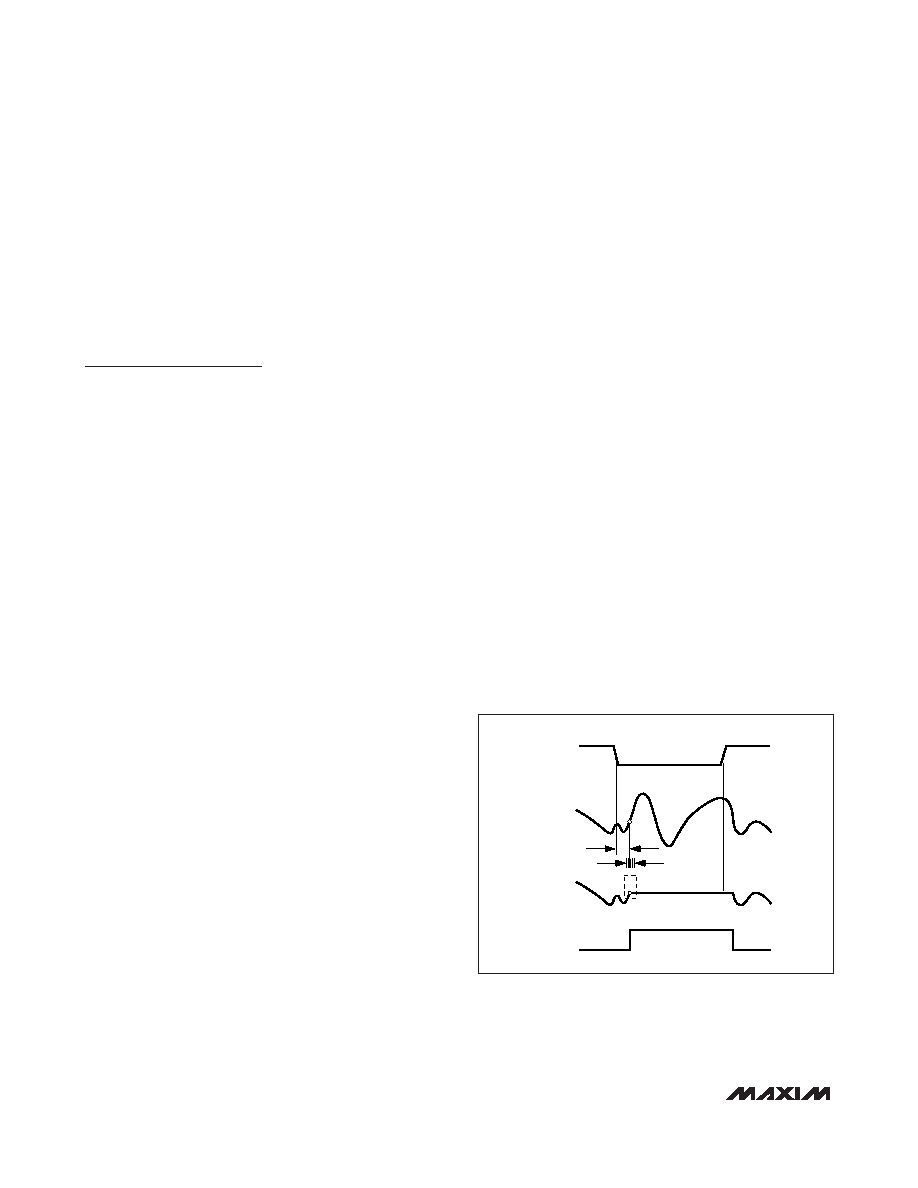
Aperture Jitter
Figure 12 depicts the aperture jitter (tAJ), which is the
sample-to-sample variation in the aperture delay.
Aperture Delay
Aperture delay (tAD) is the time defined between the
falling edge of the sampling clock and the instant when
an actual sample is taken (Figure 12).
Signal-to-Noise Ratio (SNR)
For a waveform perfectly reconstructed from digital
samples, the theoretical maximum SNR is the ratio of
the full-scale analog input (RMS value) to the RMS
quantization error (residual error). The ideal, theoretical
minimum A/D noise is caused by quantization error only
and results directly from the ADC’s resolution (N bits):
SNR(MAX) = (6.02 x N + 1.76)dB
In reality, there are other noise sources besides quanti-
zation noise: thermal noise, reference noise, clock jitter,
etc. SNR is computed by taking the ratio of the RMS
signal to the RMS noise, which includes all spectral
components minus the fundamental, the first five har-
monics, and the DC offset.
HOLD
ANALOG
INPUT
SAMPLED
DATA (T/H)
T/H
tAD
tAJ
TRACK
CLK
Figure 12. T/H Aperture Timing
相关PDF资料 |
PDF描述 |
|---|---|
| 211769-1 | CONN RECEPT CPC 9POS REV SER 1 |
| MAX1496EPI+ | IC ADC 3.5DIGIT LED DRVR 28-DIP |
| PT06A-14-18P | CONN PLUG 18POS W/PINS SOLDER |
| 206613-1 | CONN RECEPT CPC 22POS STD SER 4 |
| MAX1237EUA+ | IC ADC 12-BIT 94KSPS 8-UMAX |
相关代理商/技术参数 |
参数描述 |
|---|---|
| MAX1444EHJ/V+ | 功能描述:模数转换器 - ADC ANALOG TO DIGITAL CONVERTER RoHS:否 制造商:Texas Instruments 通道数量:2 结构:Sigma-Delta 转换速率:125 SPs to 8 KSPs 分辨率:24 bit 输入类型:Differential 信噪比:107 dB 接口类型:SPI 工作电源电压:1.7 V to 3.6 V, 2.7 V to 5.25 V 最大工作温度:+ 85 C 安装风格:SMD/SMT 封装 / 箱体:VQFN-32 |
| MAX1444EHJ/V+T | 功能描述:模数转换器 - ADC 10-Bit 40Msps 3.0V Low-Power ADC with Internal Reference RoHS:否 制造商:Texas Instruments 通道数量:2 结构:Sigma-Delta 转换速率:125 SPs to 8 KSPs 分辨率:24 bit 输入类型:Differential 信噪比:107 dB 接口类型:SPI 工作电源电压:1.7 V to 3.6 V, 2.7 V to 5.25 V 最大工作温度:+ 85 C 安装风格:SMD/SMT 封装 / 箱体:VQFN-32 |
| MAX1444EHJ+ | 功能描述:模数转换器 - ADC 10-Bit 40Msps 3V High Speed ADC RoHS:否 制造商:Texas Instruments 通道数量:2 结构:Sigma-Delta 转换速率:125 SPs to 8 KSPs 分辨率:24 bit 输入类型:Differential 信噪比:107 dB 接口类型:SPI 工作电源电压:1.7 V to 3.6 V, 2.7 V to 5.25 V 最大工作温度:+ 85 C 安装风格:SMD/SMT 封装 / 箱体:VQFN-32 |
| MAX1444EHJ+T | 功能描述:模数转换器 - ADC 10-Bit 40Msps 3V High Speed ADC RoHS:否 制造商:Texas Instruments 通道数量:2 结构:Sigma-Delta 转换速率:125 SPs to 8 KSPs 分辨率:24 bit 输入类型:Differential 信噪比:107 dB 接口类型:SPI 工作电源电压:1.7 V to 3.6 V, 2.7 V to 5.25 V 最大工作温度:+ 85 C 安装风格:SMD/SMT 封装 / 箱体:VQFN-32 |
| MAX1444EHJ-T | 功能描述:模数转换器 - ADC RoHS:否 制造商:Texas Instruments 通道数量:2 结构:Sigma-Delta 转换速率:125 SPs to 8 KSPs 分辨率:24 bit 输入类型:Differential 信噪比:107 dB 接口类型:SPI 工作电源电压:1.7 V to 3.6 V, 2.7 V to 5.25 V 最大工作温度:+ 85 C 安装风格:SMD/SMT 封装 / 箱体:VQFN-32 |
发布紧急采购,3分钟左右您将得到回复。