- 您现在的位置:买卖IC网 > PDF目录16779 > MAX1620EEE+ (Maxim Integrated Products)IC LCD BIAS SUPP DGTL ADJ 16QSOP PDF资料下载
参数资料
| 型号: | MAX1620EEE+ |
| 厂商: | Maxim Integrated Products |
| 文件页数: | 10/20页 |
| 文件大小: | 0K |
| 描述: | IC LCD BIAS SUPP DGTL ADJ 16QSOP |
| 产品培训模块: | Lead (SnPb) Finish for COTS Obsolescence Mitigation Program |
| 标准包装: | 100 |
| 应用: | LCD 显示器 |
| 电流 - 电源: | 150µA |
| 电源电压: | 3 V ~ 5.5 V |
| 工作温度: | -40°C ~ 85°C |
| 安装类型: | 表面贴装 |
| 封装/外壳: | 16-SSOP(0.154",3.90mm 宽) |
| 供应商设备封装: | 16-QSOP |
| 包装: | 管件 |
| 产品目录页面: | 1410 (CN2011-ZH PDF) |
�� �
�
�Digitally� Adjustable� LCD� Bias� Supplies�
�I� OUT� =�
�� I� PK� � V� BATT� /� V� OUT�
�_______________Detailed Description�
�The� MAX1620/MAX1621� are� step-up� power� controllers�
�that� drive� an� external� N-channel� FET� or� NPN� transistor�
�to� convert� power� from� a� 1.8V� to� 20V� battery� to� a� higher�
�positive� or� negative� voltage.� They� are� configured� as�
�negative-output,� inverting� power� controllers� with� one�
�additional� diode� and� one� additional� capacitor.� Either�
�configuration� ’s� output� voltage� can� be� adjusted� with�
�external� resistors,� or� digitally� adjusted� with� an� internal�
�digital-to-analog� converter� (DAC).� The� MAX1620� uses�
�pin-defined� controls� for� the� DAC,� while� the� MAX1621�
�communicates� with� the� DAC� via� the� SMBus?� interface.�
�Operating� Principle�
�The� MAX1620/MAX1621� operate� in� discontinuous-�
�conduction� mode� (where� the� inductor� current� ramps� to�
�zero� by� the� end� of� each� switching� cycle)� and� with� a�
�constant� peak� current,� without� requiring� a� current-�
�sense� resistor.� Switch� on-time� is� inversely� proportional�
�to� the� input� voltage� V� BATT� by� a� microsecond-volt� con-�
�stant,� or� k-factor,� of� 20μs-V� (e.g.,� for� V� BATT� =� 10V,�
�on-time� =� 2μs).�
�For� an� ideal� boost� converter� operating� in� discontinu-�
�ous-conduction� mode� (no� power� losses),� output� current�
�is� proportional� to� input� voltage� and� peak� inductor� current:�
�1�
�2�
�I� PK� is� proportional� to� on-time� (t� ON� ),� which,� for� these�
�parts,� is� determined� by� the� k-factor:�
�I� PK� =� k-factor� /� L�
�2V�
�Discontinuous� conduction� is� detected� by� monitoring� the�
�LX� node� voltage.� When� the� inductor’s� energy� is� com-�
�pletely� delivered,� the� LX� node� voltage� snaps� back� to�
�the� BATT� voltage.� When� this� crossing� is� sensed,� anoth-�
�er� pulse� is� issued� if� the� output� is� still� out� of� regulation.�
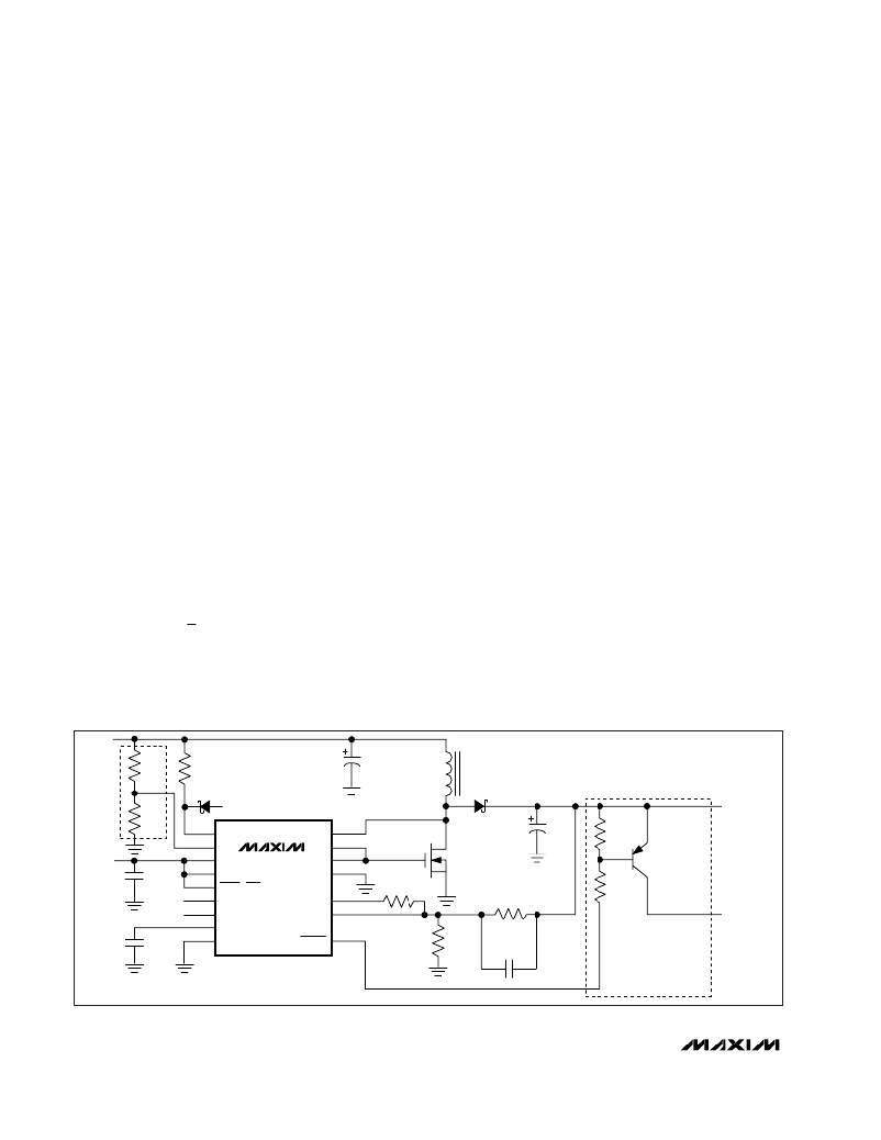
�Positive� Output� Voltage�
�To� select� a� positive� output� voltage,� tie� the� polarity� pin�
�(POL)� to� V� DD� and� use� the� typical� boost� topology� shown�
�in� Figure� 4.� FB� regulation� voltage� is� 1.5V.� For� optimum�
�stability,� V� OUT� should� be� greater� than� 1.1� (V� BATT� ).�
�Negative� Output� Voltage�
�To� select� a� negative� output� voltage,� tie� POL� to� GND�
�(Figure� 5).� In� this� configuration,� the� internal� error� amplifi-�
�er’s� output� is� inverted� to� provide� the� correct� feedback�
�polarity.� FB� regulation� voltage� is� 0V.� D1,� D2,� C4,� and� C5�
�form� an� inverting� charge� pump� to� generate� the� negative�
�voltage.� This� allows� application� of� the� positive� boost�
�switching� topology� to� negative� output� voltages.�
�The� negative� output� circuit� has� two� possible� connec-�
�tions.� In� the� standard� connection,� D1’s� cathode� is� con-�
�nected� to� BATT.� This� connection� features� the� best�
�output� ripple� performance,� but� ?� V� OUT� ?� must� be� limited�
�to� no� more� than� 27V� -� 1.1(V� BATT� ).� If� a� larger� negative�
�voltage� is� needed,� an� alternative� connection� allows� a�
�maximum� negative� output� of� -27V,� but� with� the� addition-�
�al� constraint� that� ?� V� OUT� ?� >� 1.1V� BATT� .� To� use� the� alter-�
�native� circuit,� connect� D1’s� cathode� to� ground� rather�
�than� BATT� (Figure� 6).� Increase� C4� to� 2.2� μ� F� to� improve�
�output� ripple� performance.�
�The� negative� charge� pump� limits� the� output� current� to�
�the� charge� transferred� each� cycle� multiplied� by� the�
�TO�
�12V�
�R1�
�360k�
�R8�
�10k�
�C3�
�22� μ� F�
�L1�
�100� μ� H�
�D3� 1N6263� (ANY� SCHOTTKY)�
�U1�
�C6�
�100pF�
�3V�
�TO�
�5.5V�
�R2�
�100k�
�C1�
�0.1� μ� F�
�C2�
�0.1� μ� F�
�3�
�5�
�11�
�7�
�4�
�1�
�2�
�6�
�12�
�TO� REF�
�BATT�
�POK�
�V� DD� MAX1620�
�POL� MAX1621�
�SHDN� (SUS)�
�DN� (SDA)�
�UP� (SCL)�
�REF�
�AGND�
�LX�
�DHI�
�DLO�
�PGND�
�DOUT�
�FB�
�LCDON�
�14�
�16�
�15�
�13�
�10�
�9�
�8�
�R3�
�300k�
�D1�
�MBRS0540�
�N1�
�MMFT3055VL�
�R5�
�2.2M�
�R4�
�300k�
�C5�
�22� μ� F�
�R6�
�56k�
�R7�
�56k�
�Q1�
�MMBT2907�
�12.5V�
�TO�
�23.5V� OUT�
�VOUTSW�
�(� )� ARE� FOR� MAX1621.�
�NOTE:� CONNECTIONS� TO� DIGITAL� INPUTS� NOT� SHOWN.�
�Figure� 4.� Typical� Operating� Circuit—Positive� Output�
�OPTIONAL�
�10�
�______________________________________________________________________________________�
�相关PDF资料 |
PDF描述 |
|---|---|
| GEC15DRYI-S734 | CONN EDGECARD 30POS DIP .100 SLD |
| EEM18DREF | CONN EDGECARD 36POS .156 EYELET |
| V24B28E150BF2 | CONVERTER MOD DC/DC 28V 150W |
| V300C24E150BG | CONVERTER MOD DC/DC 24V 150W |
| RBC22DRTN-S13 | CONN EDGECARD 44POS .100 EXTEND |
相关代理商/技术参数 |
参数描述 |
|---|---|
| MAX1620EEE+ | 功能描述:其他电源管理 Digitally Adjustable LCD Bias Supply RoHS:否 制造商:Texas Instruments 输出电压范围: 输出电流:4 mA 输入电压范围:3 V to 3.6 V 输入电流: 功率耗散: 工作温度范围:- 40 C to + 110 C 安装风格:SMD/SMT 封装 / 箱体:VQFN-48 封装:Reel |
| MAX1620EEE+T | 功能描述:LCD 驱动器 Digitally Adjustable LCD Bias Supply RoHS:否 制造商:Maxim Integrated 数位数量:4.5 片段数量:30 最大时钟频率:19 KHz 工作电源电压:3 V to 3.6 V 最大工作温度:+ 85 C 最小工作温度:- 20 C 封装 / 箱体:PDIP-40 封装:Tube |
| MAX1620EEE-T | 功能描述:直流/直流开关转换器 RoHS:否 制造商:STMicroelectronics 最大输入电压:4.5 V 开关频率:1.5 MHz 输出电压:4.6 V 输出电流:250 mA 输出端数量:2 最大工作温度:+ 85 C 安装风格:SMD/SMT |
| MAX1620EPE+ | 制造商:Maxim Integrated Products 功能描述:- Rail/Tube |
| MAX1620ESE+ | 制造商:Maxim Integrated Products 功能描述:- Rail/Tube |
发布紧急采购,3分钟左右您将得到回复。