- 您现在的位置:买卖IC网 > PDF目录383329 > MAX1621EEE (MAXIM INTEGRATED PRODUCTS INC) Digitally Adjustable LCD Bias Supplies PDF资料下载
参数资料
| 型号: | MAX1621EEE |
| 厂商: | MAXIM INTEGRATED PRODUCTS INC |
| 元件分类: | 稳压器 |
| 英文描述: | Digitally Adjustable LCD Bias Supplies |
| 中文描述: | SWITCHING CONTROLLER, 200 kHz SWITCHING FREQ-MAX, PDSO16 |
| 封装: | 0.150 INCH, 0.025 INCH PITCH, QSOP-16 |
| 文件页数: | 10/20页 |
| 文件大小: | 253K |
| 代理商: | MAX1621EEE |
M
Digitally Adjustable LCD Bias S upplies
10
______________________________________________________________________________________
R1
360k
2V
TO
12V
BATT
POK
V
DD
POL
SHDN (SUS)
DN (SDA)
UP (SCL)
REF
AGND
D1
MBRS0540
N1
MMFT3055VL
Q1
MMBT2907
3
5
O
11
7
4
1
2
6
12
( ) ARE FOR MAX1621.
NOTE:
CONNECTIONS TODIGITAL INPUTS NOT SHOWN.
14
16
15
13
R3
300k
R4
300k
R5
2.2M
C6
100pF
10
9
8
LX
DHI
DLO
PGND
DOUT
FB
LCDON
3V
TO
5.5V
C1
0.1
μ
F
C2
0.1
μ
F
R2
100k
R8
10k
TOREF
D3 1N6263 (ANY SCHOTTKY)
C3
22
μ
F
C5
22
μ
F
12.5V
TO
23.5V OUT
VOUTSW
OPTIONAL
R6
56k
R7
56k
L1
100
μ
H
MAX1620
MAX1621
U1
_______________Detailed Desc ription
The MAX1620/MAX1621 are step-up power controllers
that drive an external N-channel FET or NPN transistor
to convert power from a 1.8V to 20V battery to a higher
positive or negative voltage. They are configured as
negative-output, inverting power controllers with one
additional diode and one additional capacitor. Either
configuration’s output voltage can be adjusted with
external resistors, or digitally adjusted with an internal
digital-to-analog converter (DAC). The MAX1620 uses
pin-defined controls for the DAC, while the MAX1621
communicates with the DAC via the SMBus interface.
Operating Princ iple
The MAX1620/MAX1621 operate in discontinuous-
conduction mode (where the inductor current ramps to
zero by the end of each switching cycle) and with a
constant peak current, without requiring a current-
sense resistor. Switch on-time is inversely proportional
to the input voltage V
BATT
by a microsecond-volt con-
stant, or k-factor, of 20μs-V (e.g., for V
BATT
= 10V,
on-time = 2μs).
For an ideal boost converter operating in discontinu-
ous-conduction mode (no power losses), output current
is proportional to input voltage and peak inductor current:
I
PK
is proportional to on-time (t
ON
), which, for these
parts, is determined by the k-factor:
I
PK
= k-factor / L
Discontinuous conduction is detected by monitoring the
LX node voltage. When the inductor’s energy is com-
pletely delivered, the LX node voltage snaps back to
the BATT voltage. When this crossing is sensed, anoth-
er pulse is issued if the output is still out of regulation.
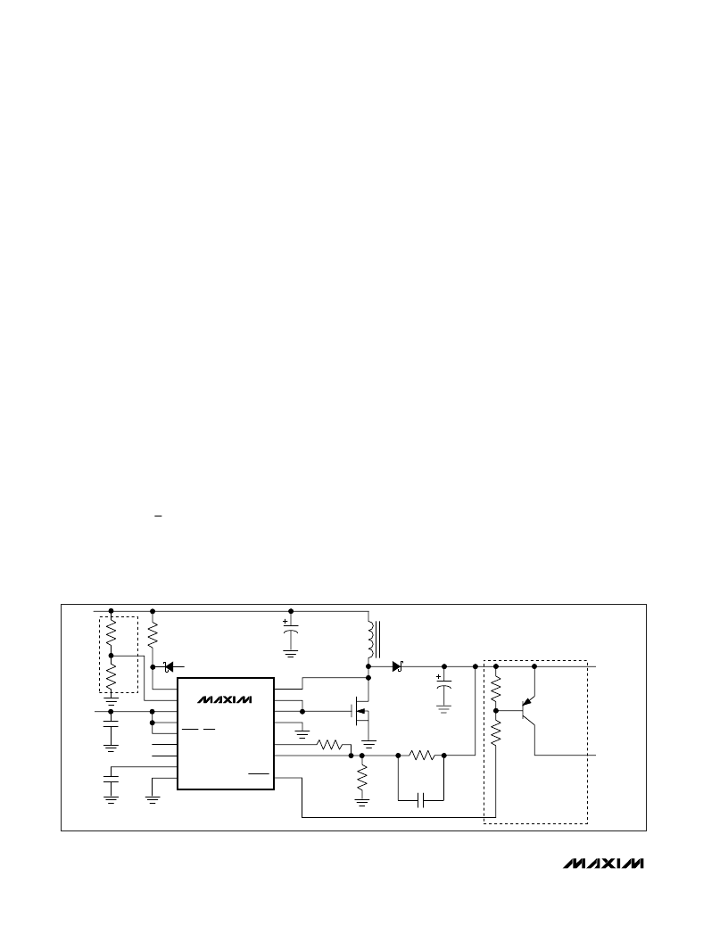
Positive Output V oltage
To select a positive output voltage, tie the polarity pin
(POL) to V
DD
and use the typical boost topology shown
in Figure 4. FB regulation voltage is 1.5V. For optimum
stability, V
OUT
should be greater than 1.1 (V
BATT
).
Negative Output V oltage
To select a negative output voltage, tie POL to GND
(Figure 5). In this configuration, the internal error amplifi-
er’s output is inverted to provide the correct feedback
polarity. FB regulation voltage is 0V. D1, D2, C4, and C5
form an inverting charge pump to generate the negative
voltage. This allows application of the positive boost
switching topology to negative output voltages.
The negative output circuit has two possible connec-
tions. In the standard connection, D1’s cathode is con-
nected to BATT. This connection features the best
output ripple performance, but
V
OUT
must be limited
to no more than 27V - 1.1(V
BATT
). If a larger negative
voltage is needed, an alternative connection allows a
maximum negative output of -27V, but with the addition-
al constraint that
V
OUT
> 1.1V
BATT
. To use the alter-
native circuit, connect D1’s cathode to ground rather
than BATT (Figure 6). Increase C4 to 2.2
μ
F to improve
output ripple performance.
The negative charge pump limits the output current to
the charge transferred each cycle multiplied by the
I
1
2
I
V
/ V
OUT
PK
BATT
OUT
=
×
×
Figure 4. Typical Operating Circuit—Positive Output
相关PDF资料 |
PDF描述 |
|---|---|
| MAX1623 | 3A, Low-Voltage, Step-Down Regulator with Synchronous Rectification and Internal Switches |
| MAX1623EAP | 3A, Low-Voltage, Step-Down Regulator with Synchronous Rectification and Internal Switches |
| MAX1624 | High-Speed Step-Down Controllers with Synchronous Rectification for CPU Power |
| MAX1625ESE | High-Speed Step-Down Controllers with Synchronous Rectification for CPU Power |
| MAX1624-MAX1625 | High-Speed Step-Down Controllers with Synchronous Rectification for CPU Power |
相关代理商/技术参数 |
参数描述 |
|---|---|
| MAX1621EEE+ | 功能描述:其他电源管理 Digitally Adjustable LCD Bias Supply RoHS:否 制造商:Texas Instruments 输出电压范围: 输出电流:4 mA 输入电压范围:3 V to 3.6 V 输入电流: 功率耗散: 工作温度范围:- 40 C to + 110 C 安装风格:SMD/SMT 封装 / 箱体:VQFN-48 封装:Reel |
| MAX1621EEE+T | 功能描述:LCD 驱动器 Digitally Adjustable LCD Bias Supply RoHS:否 制造商:Maxim Integrated 数位数量:4.5 片段数量:30 最大时钟频率:19 KHz 工作电源电压:3 V to 3.6 V 最大工作温度:+ 85 C 最小工作温度:- 20 C 封装 / 箱体:PDIP-40 封装:Tube |
| MAX1621EEE-T | 功能描述:显示驱动器和控制器 RoHS:否 制造商:Panasonic Electronic Components 工作电源电压:2.7 V to 5.5 V 最大工作温度: 安装风格:SMD/SMT 封装 / 箱体:QFN-44 封装:Reel |
| MAX1621EPE+ | 制造商:Maxim Integrated Products 功能描述:- Rail/Tube |
| MAX1621ESE+ | 制造商:Maxim Integrated Products 功能描述:- Rail/Tube |
发布紧急采购,3分钟左右您将得到回复。