- 您现在的位置:买卖IC网 > Datasheet目录340 > MAX16838AUP+ (Maxim Integrated)IC LED DRIVR HIGH BRIGHT 20TSSOP Datasheet资料下载
参数资料
| 型号: | MAX16838AUP+ |
| 厂商: | Maxim Integrated |
| 文件页数: | 15/21页 |
| 文件大小: | 0K |
| 描述: | IC LED DRIVR HIGH BRIGHT 20TSSOP |
| 产品培训模块: | Lead (SnPb) Finish for COTS Obsolescence Mitigation Program |
| 标准包装: | 74 |
| 恒定电流: | 是 |
| 拓扑: | 线性(LDO),PWM,SEPIC,递升(升压) |
| 输出数: | 2 |
| 内部驱动器: | 是 |
| 类型 - 主要: | 车载,背光 |
| 类型 - 次要: | 高亮度 LED(HBLED) |
| 频率: | 200kHz ~ 2MHz |
| 电源电压: | 4.75 V ~ 40 V,4.55 V ~ 5.5 V |
| 输出电压: | 4.75 V ~ 5.25 V |
| 安装类型: | 表面贴装 |
| 封装/外壳: | 20-TSSOP(0.173",4.40mm 宽)裸露焊盘 |
| 供应商设备封装: | 20-TSSOP-EP |
| 包装: | 管件 |
| 工作温度: | -40°C ~ 125°C |
�� �
�
�MAX16838�
�Integrated,� 2-Channel,� High-Brightness� LED� Driver�
�with� High-Voltage� Boost� and� SEPIC� Controller�
�Enable� (EN)�
�EN� is� a� logic� input� that� completely� shuts� down� the�
�device� when� connected� to� logic-low,� reducing� the�
�current� consumption� of� the� device� to� less� than� 15� F� A�
�(typ).� The� logic� threshold� at� EN� is� 1.24V� (typ).� The� volt-�
�age� at� EN� must� exceed� 1.24V� before� any� operation� can�
�commence.� There� is� a� 71mV� hysteresis� on� EN.� The� EN�
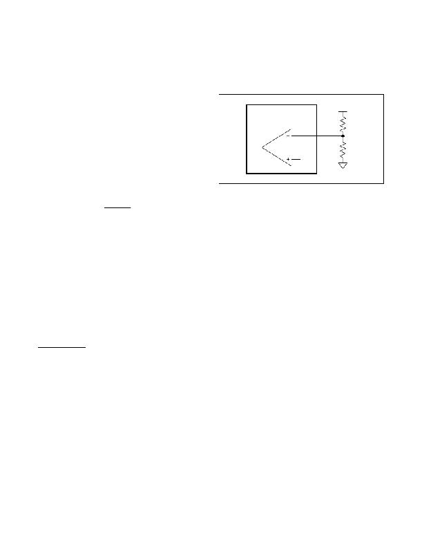
�input� also� allows� programming� the� supply� input� UVLO�
�threshold� using� an� external� voltage-divider� to� sense� the�
�MAX16838�
�1.24V�
�EN�
�V� IN�
�R1� EN�
�R2� EN�
�input� voltage,� as� shown� in� Figure� 3.� Use� the� following�
�V� ON�
�equation� to� calculate� the� value� of� R1� EN� and� R2� EN� in�
�Figure� 3:�
�?� ?�
�R1� EN�
�=� ?� ?� 1� ?� � R2� EN�
�?� V� UVLOIN� ?�
�where� V� UVLOIN� is� the� EN� rising� threshold� (1.24V)� and�
�V� ON� is� the� desired� input� startup� voltage.� Choose� an�
�R2� EN� between� 10k� I� and� 50k� I� .� Connect� EN� to� IN� if� not�
�used.�
�Current� Foldback�
�The� MAX16838� includes� a� current-foldback� feature� to�
�limit� the� input� current� at� low� V� IN� .� Connect� a� resistor-�
�divider� between� IN,� CFB,� and� SGND� to� set� the� current-�
�foldback� threshold.� When� the� voltage� at� CFB� goes� below�
�1.23V,� then� the� LED� current� starts� reducing� proportion-�
�ally� to� V� CFB� .�
�This� feature� can� also� be� used� for� analog� dimming� of� the�
�LEDs.� Connect� CFB� to� V� CC� to� disable� this� feature.�
�Applications� Information�
�Boost-Circuit� Design�
�First,� determine� the� required� input� supply� voltage� range,�
�the� maximum� voltage� needed� to� drive� the� LED� strings�
�including� the� minimum� 1V� across� the� constant� LED�
�current� sink� (V� LED� ),� and� the� total� output� current� needed�
�to� drive� the� LED� strings� (I� LED� ).�
�Calculate� the� maximum� duty� cycle� (D� MAX� )� using� the�
�following� equation:�
�D� MAX� =� (V� LED� +� V� D� –� V� IN_MIN� )/(V� LED� +� V� D� )�
�where� V� D� is� the� forward� drop� of� the� rectifier� diode,�
�V� IN_MIN� is� the� minimum� input� supply� voltage,� and�
�V� LED� is� the� output� voltage.� Select� the� switching�
�frequency� (f� SW� )� depending� on� the� space,� noise,� dynam-�
�ic� response,� and� efficiency� constraints.�
�Maxim� Integrated�
�Figure� 3.� Setting� the� MAX16838� Undervoltage� Lockout�
�Threshold�
�Inductor� Selection� in� Boost� Configuration�
�Select� the� maximum� peak-to-peak� ripple� on� the� inductor�
�current� (IL� P-P� ).� Use� the� following� equations� to� calculate�
�the� maximum� average� inductor� current� (IL� AVG� )� and�
�peak� inductor� current� (IL� PEAK� ):�
�IL� AVG� =� I� LED� /(1� -� D� MAX� )�
�Assuming� IL� P-P� is� 40%� of� the� average� inductor� current:�
�IL� P-P� =� IL� AVG� x� 0.4�
�IL� PEAK� =� IL� AVG� +� IL� P-P� /2�
�Calculate� the� minimum� inductance� value� L� MIN� with� the�
�inductor� current� ripple� set� to� the� maximum� value:�
�L� MIN� =� V� IN_MIN� x� D� MAX� /(f� SW� x� IL� P-P� )�
�Choose� an� inductor� that� has� a� minimum� inductance�
�greater� than� the� calculated� L� MIN� and� current� rating�
�greater� than� IL� PEAK� .� The� recommended� saturation�
�current� limit� of� the� selected� inductor� is� 10%� higher� than�
�the� inductor� peak� current.� The� IL� P-P� can� be� chosen�
�to� have� a� higher� ripple� than� 40%.� Adjust� the� minimum�
�value� of� the� inductance� according� to� the� chosen� ripple.�
�One� fact� that� must� be� noted� is� that� the� slope� compensa-�
�tion� is� fixed� and� has� a� 120mV� peak� per� switching� cycle.�
�The� dv/dt� of� the� slope� compensation� ramp� is� 120f� SW� V/�
�F� s,� where� f� SW� is� in� kHz.� After� selecting� the� inductance�
�it� is� necessary� to� verify� that� the� slope� compensation� is�
�adequate� to� prevent� subharmonic� oscillations.� In� the�
�case� of� the� boost,� the� following� criteria� must� be� satisfied:�
�120f� SW� >� R� CS� (V� LED� -� 2V� IN_MIN� )/2L�
�where� L� is� the� inductance� value� in� F� H,� R� CS� is� the�
�current-sense� resistor� value� in� ω,� V� IN_MIN� is� the� mini-�
�mum� input� voltage� in� V,� V� LED� is� the� output� voltage,� and�
�f� SW� is� the� switching� frequency� in� kHz.�
�If� the� inductance� value� is� chosen� to� keep� the� inductor�
�in� discontinuous� conduction� mode,� the� equation� above�
�does� not� need� to� be� satisfied.�
�15�
�相关PDF资料 |
PDF描述 |
|---|---|
| MAX1698EUB | IC LED DRVR WT/CLR BCKLGT 10MSOP |
| MAX17014EVKIT+ | KIT EVAL FOR MAX17014 |
| MAX17061AETI+T | IC LED DRVR WHITE BCKLGT 28-TQFN |
| MAX17061ETI+T | IC LED DRVR WHITE BCKLGT 28-TQFN |
| MAX17105ETG+T | IC LED DRVR WHITE BCKLGT 24-TQFN |
相关代理商/技术参数 |
参数描述 |
|---|---|
| MAX16838AUP/V+ | 功能描述:LED照明驱动器 HB w/High-Voltage DC/DC Controller RoHS:否 制造商:STMicroelectronics 输入电压:11.5 V to 23 V 工作频率: 最大电源电流:1.7 mA 输出电流: 最大工作温度: 安装风格:SMD/SMT 封装 / 箱体:SO-16N |
| MAX16838AUP/V+T | 功能描述:LED照明驱动器 HB w/High-Voltage DC/DC Controller RoHS:否 制造商:STMicroelectronics 输入电压:11.5 V to 23 V 工作频率: 最大电源电流:1.7 mA 输出电流: 最大工作温度: 安装风格:SMD/SMT 封装 / 箱体:SO-16N |
| MAX16838AUP+ | 功能描述:LED照明驱动器 HB w/High-Voltage DC/DC Controller RoHS:否 制造商:STMicroelectronics 输入电压:11.5 V to 23 V 工作频率: 最大电源电流:1.7 mA 输出电流: 最大工作温度: 安装风格:SMD/SMT 封装 / 箱体:SO-16N |
| MAX16838AUP+T | 功能描述:LED照明驱动器 HB w/High-Voltage DC/DC Controller RoHS:否 制造商:STMicroelectronics 输入电压:11.5 V to 23 V 工作频率: 最大电源电流:1.7 mA 输出电流: 最大工作温度: 安装风格:SMD/SMT 封装 / 箱体:SO-16N |
| MAX16838EVKIT+ | 功能描述:LED 照明开发工具 MAX16838 evaluation kit RoHS:否 制造商:Fairchild Semiconductor 产品:Evaluation Kits 用于:FL7732 核心: 电源电压:120V 系列: 封装: |
发布紧急采购,3分钟左右您将得到回复。