- 您现在的位置:买卖IC网 > PDF目录1838 > MAX16907RAUE/V+ (Maxim Integrated Products)IC REG BUCK SYNC ADJ 3A 16TSSOP PDF资料下载
参数资料
| 型号: | MAX16907RAUE/V+ |
| 厂商: | Maxim Integrated Products |
| 文件页数: | 14/17页 |
| 文件大小: | 0K |
| 描述: | IC REG BUCK SYNC ADJ 3A 16TSSOP |
| 标准包装: | 96 |
| 类型: | 降压(降压) |
| 输出类型: | 两者兼有 |
| 输出数: | 1 |
| 输出电压: | 5V,1 V ~ 10 V |
| 输入电压: | 3.5 V ~ 36 V |
| PWM 型: | 电流模式 |
| 频率 - 开关: | 1MHz ~ 2.2MHz |
| 电流 - 输出: | 3A |
| 同步整流器: | 无 |
| 工作温度: | -40°C ~ 125°C |
| 安装类型: | * |
| 封装/外壳: | * |
| 包装: | * |
| 供应商设备封装: | * |
�� �
�
�MAX16907�
�36V,� 2.2MHz� Step-Down� Converter�
�with� Low� Operating� Current�
�the� inductor� energy� while� transitioning� from� full-load�
�to� no-load� conditions� without� tripping� the� overvoltage�
�fault� protection.� When� using� high-capacitance,� low-ESR�
�capacitors,� the� filter� capacitor’s� ESR� dominates� the�
�output-voltage� ripple.� So� the� size� of� the� output� capaci-�
�tor� depends� on� the� maximum� ESR� required� to� meet� the�
�output-voltage� ripple� (V� RIPPLE(P-P)� )� specifications:�
�V� RIPPLE(P-P)� =� ESR� � I� LOAD(MAX)� � LIR�
�The� actual� capacitance� value� required� relates� to� the�
�physical� size� needed� to� achieve� low� ESR,� as� well� as�
�to� the� chemistry� of� the� capacitor� technology.� Thus,� the�
�capacitor� is� usually� selected� by� ESR� and� voltage� rating�
�rather� than� by� capacitance� value.�
�When� using� low-capacity� filter� capacitors,� such� as�
�ceramic� capacitors,� size� is� usually� determined� by� the�
�capacity� needed� to� prevent� voltage� droop� and� volt-�
�age� rise� from� causing� problems� during� load� transients.�
�Generally,� once� enough� capacitance� is� added� to� meet�
�the� overshoot� requirement,� undershoot� at� the� rising� load�
�edge� is� no� longer� a� problem.� However,� low-capacity� filter�
�capacitors� typically� have� high-ESR� zeros� that� can� affect�
�the� overall� stability.�
�Rectifier� Selection�
�The� device� requires� an� external� Schottky� diode� recti-�
�fier� as� a� freewheeling� diode.� Connect� this� rectifier� close�
�to� the� device� using� short� leads� and� short� PCB� traces.�
�Choose� a� rectifier� with� a� voltage� rating� greater� than� the�
�maximum� expected� input� voltage,� V� SUPSW� .� Use� a� low�
�forward-voltage-drop� Schottky� rectifier� to� limit� the� nega-�
�tive� voltage� at� LX.� Avoid� higher� than� necessary� reverse-�
�voltage� Schottky� rectifiers� that� have� higher� forward-�
�voltage� drops.�
�V� OUT�
�R� 1�
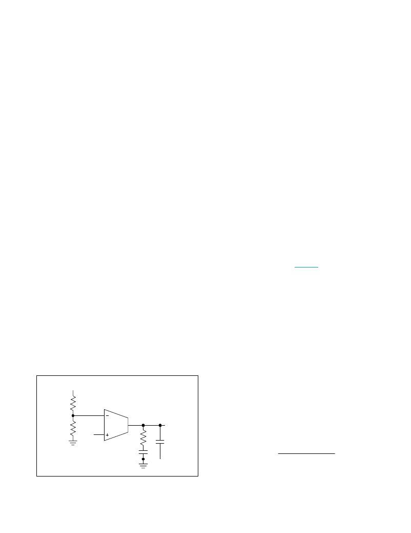
�Compensation� Network�
�The� device� uses� an� internal� transconductance� error�
�amplifier� with� its� inverting� input� and� its� output� available�
�to� the� user� for� external� frequency� compensation.� The�
�output� capacitor� and� compensation� network� determine�
�the� loop� stability.� The� inductor� and� the� output� capaci-�
�tor� are� chosen� based� on� performance,� size,� and� cost.�
�Additionally,� the� compensation� network� optimizes� the�
�control-loop� stability.�
�The� controller� uses� a� current-mode� control� scheme� that�
�regulates� the� output� voltage� by� forcing� the� required� current�
�through� the� external� inductor.� The� device� uses� the� volt-�
�age� drop� across� the� high-side� MOSFET� to� sense� inductor�
�current.� Current-mode� control� eliminates� the� double� pole�
�in� the� feedback� loop� caused� by� the� inductor� and� output�
�capacitor,� resulting� in� a� smaller� phase� shift� and� requiring�
�less� elaborate� error-amplifier� compensation� than� voltage-�
�mode� control.� Only� a� simple� single-series� resistor� (R� C� )�
�and� capacitor� (C� C� )� are� required� to� have� a� stable,� high-�
�bandwidth� loop� in� applications� where� ceramic� capacitors�
�are� used� for� output� filtering� (� Figure� 3� ).� For� other� types� of�
�capacitors,� due� to� the� higher� capacitance� and� ESR,� the�
�frequency� of� the� zero� created� by� the� capacitance� and�
�ESR� is� lower� than� the� desired� closed-loop� crossover� fre-�
�quency.� To� stabilize� a� nonceramic� output� capacitor� loop,�
�add� another� compensation� capacitor� (C� F� )� from� COMP� to�
�GND� to� cancel� this� ESR� zero.�
�The� basic� regulator� loop� is� modeled� as� a� power� modula-�
�tor,� output� feedback� divider,� and� an� error� amplifier.� The�
�power� modulator� has� a� DC� gain� set� by� g� mc� x� R� LOAD� ,�
�with� a� pole� and� zero� pair� set� by� R� LOAD� ,� the� output�
�capacitor� (C� OUT� ),� and� its� ESR.� The� following� equations�
�allow� to� approximate� the� value� for� the� gain� of� the� power�
�modulator� (GAIN� MOD(DC)� ),� neglecting� the� effect� of� the�
�ramp� stabilization.� Ramp� stabilization� is� necessary� when�
�the� duty� cycle� is� above� 50%� and� is� internally� done� for�
�the� device.�
�GAIN� MOD(DC)� =� g� mc� � R� LOAD�
�where� R� LOAD� =� V� OUT� /I� LOUT(MAX)� in� I� ,� and� g� mc� =� 3S.�
�f� pMOD� =�
�R� 2�
�V� REF�
�g� m�
�R� C�
�C� C�
�COMP�
�C� F�
�In� a� current-mode� step-down� converter,� the� output�
�capacitor,� its� ESR,� and� the� load� resistance� introduce� a�
�pole� at� the� following� frequency:�
�1�
�2� π� ×� C� OUT� ×� R� LOAD�
�Figure� 3.� Compensation� Network�
�Maxim� Integrated�
�14�
�相关PDF资料 |
PDF描述 |
|---|---|
| MAX16909RAUE/V+ | IC REG BUCK 5V/ADJ 3A 16TSSOP |
| MAX16910CASA8/V+ | IC REG LDO 3.3V/5V/ADJ .2A 8SOIC |
| MAX16913GEE/V+ | IC CURRENT SENSE SWITCH 16QSOP |
| MAX16915AUB/V+ | IC CTRLR IDEAL DIODE 10UMAX |
| MAX16920BATJ/V+ | IC PMIC MULT-OUTPUT AUTO 32TQFN |
相关代理商/技术参数 |
参数描述 |
|---|---|
| MAX16907SATE/V+ | 功能描述:直流/直流开关转换器 36V 2.2MHz Step Down Converter RoHS:否 制造商:STMicroelectronics 最大输入电压:4.5 V 开关频率:1.5 MHz 输出电压:4.6 V 输出电流:250 mA 输出端数量:2 最大工作温度:+ 85 C 安装风格:SMD/SMT |
| MAX16907SATE/V+T | 功能描述:直流/直流开关转换器 36V 2.2MHz Step-Down Converter RoHS:否 制造商:STMicroelectronics 最大输入电压:4.5 V 开关频率:1.5 MHz 输出电压:4.6 V 输出电流:250 mA 输出端数量:2 最大工作温度:+ 85 C 安装风格:SMD/SMT |
| MAX16907SATE+ | 制造商:Maxim Integrated Products 功能描述:- Rail/Tube |
| MAX16907SATE+T | 制造商:Maxim Integrated Products 功能描述:- Tape and Reel |
| MAX16907SAUE/V+ | 功能描述:直流/直流开关转换器 36V 2.2MHz Step-Down Converter RoHS:否 制造商:STMicroelectronics 最大输入电压:4.5 V 开关频率:1.5 MHz 输出电压:4.6 V 输出电流:250 mA 输出端数量:2 最大工作温度:+ 85 C 安装风格:SMD/SMT |
发布紧急采购,3分钟左右您将得到回复。