- 您现在的位置:买卖IC网 > PDF目录16574 > MAX16946GEE/V+T (Maxim Integrated Products)IC REG LDO/SWITCH ADJ 16QSOP PDF资料下载
参数资料
| 型号: | MAX16946GEE/V+T |
| 厂商: | Maxim Integrated Products |
| 文件页数: | 17/21页 |
| 文件大小: | 0K |
| 描述: | IC REG LDO/SWITCH ADJ 16QSOP |
| 其它有关文件: | Automotive Product Guide |
| 产品培训模块: | Lead (SnPb) Finish for COTS Obsolescence Mitigation Program |
| 标准包装: | 2,500 |
| 应用: | 汽车系统,远程电源 |
| 电流 - 电源: | 2.1mA |
| 电源电压: | 4.5 V ~ 18 V |
| 工作温度: | -40°C ~ 105°C |
| 安装类型: | 表面贴装 |
| 封装/外壳: | 16-LSSOP(0.154",3.90mm 宽) |
| 供应商设备封装: | 16-QSOP 裸露焊盘 |
| 包装: | 带卷 (TR) |
�� �
�
�MAX16946/MAX16947�
�Remote� Antenna,� Current-Sense� and�
�LDO/Switches�
�?� V� OUT� ?�
�Current-Limit� Threshold� Selection�
�A� resistive� divider� between� REF,� LIM,� and� GND� sets� the�
�current-limit� threshold.� See� Figure� 6.�
�Use� the� following� formula� to� set� the� desired� current-limit�
�R� 2� =�
�R� 1�
�?� V� FB� ?�
�?� ?� 1� ?�
�V� REF�
�?� R� SENSE� � I� CL� � A� V� +� 0.4V�
�?� 1� ?�
�threshold:�
�R� 2� =�
�?�
�?�
�R� 1�
�?�
�?�
�Select� R� 1� so� that� the� maximum� input� bias� current� at� FB�
�is� negligible� compared� to� the� total� current� going� through�
�R� 1� .�
�R� 2� =�
�?� 0.5� ?� � 0.120A� � 26V/V+0.4V� ?� 1� ?�
�where� I� CL� is� the� desired� current-limit� threshold,� A� V� is� the�
�current-sense� amplifier� gain� (26V/V� typ),� and� V� REF� is� the�
�reference� voltage� (3V� typ).� Size� R� 1� and� R� 2� large� enough�
�so� that� the� equivalent� resistance� of� the� resistive� dividers�
�used� to� set� the� open-load� and� current-limit� thresholds�
�does� not� exceed� the� REF� output� 100� F� A� drive� capability.�
�For� example,� to� set� the� current-limit� threshold� at� 120mA,�
�using� a� 0.5� I� sense� resistor,� use� the� following� method� to�
�calculate� the� value� of� R� 1� and� R� 2� :�
�R� 1�
�?� 3V� ?�
�?� ?�
�Choose� R� 1� =� 83k� I� and� calculate� R� 2� as� 156k� I� .�
�Using� an� External� Reference�
�Use� an� external� reference� with� resistive� dividers� as� an�
�alternative� means� of� setting� the� current-limit� and� open-�
�load� current� thresholds.� The� equations� shown� in� the�
�Open-Load� Current� Threshold� Selection� and� Current-�
�Limit� Threshold� Selection� sections� are� still� applicable�
�when� using� an� external� reference.� In� those� equations,�
�set� V� REF� equal� to� the� voltage� of� the� external� reference.�
�When� using� the� devices’� 3V� reference,� the� maximum�
�voltage� at� LIM� is� V� LIM� =� 3V� and� is� obtained� by� connect-�
�ing� LIM� to� REF.� When� using� an� external� reference,� set�
�the� voltage� at� LIM� to� no� greater� than� V� LIM(MAX)� =� 3.65V.�
�Fixed/Adjustable� Output� Voltage�
�The� MAX16946� is� configurable� to� provide� a� fixed� 8.5V�
�output� or� as� an� adjustable� LDO� with� an� output� between�
�Compensation� Capacitor�
�Compensate� the� LDO� regulator� by� bypassing� COMP� to�
�GND� with� a� 0.1� F� F� ceramic� capacitor.�
�Input� Capacitor�
�Connect� a� low-leakage� ceramic� capacitor� from� IN� to�
�GND� to� limit� the� input-voltage� drop� during� momentary�
�output� short-circuit� conditions� and� to� protect� the� device�
�against� transients� due� to� inductance� in� the� IN� line.� For�
�example,� use� at� least� a� 0.1� F� F� ceramic� capacitor� if� the�
�input� inductance� (including� any� stray� inductance)� is�
�estimated� to� be� 20� F� H.� Larger� capacitor� values� reduce�
�the� voltage� undershoot� and� voltage� overshoot� in� case� of�
�reverse� current� at� the� input.�
�Output� Capacitor�
�In� an� analogous� fashion� to� the� input� capacitor,� an� output�
�capacitor� protects� the� device� against� transients� due� to�
�any� series� inductance� in� the� output.� Under� no� conditions�
�should� the� voltage� on� OUT� go� below� -0.3V� as� specified�
�in� the� Absolute� Maximum� Ratings� section.� A� Schottky�
�diode� is� required� to� clamp� transients� that� go� below�
�ground.� For� example,� with� a� 2.2mH� series� inductance,�
�to� avoid� excessive� ringing� at� the� output,� bypass� OUT� to�
�GND� with� not� more� than� 0.1� F� F� capacitance.� Additionally,�
�bypassing� OUT� to� GND� with� a� 2.2� F� F� ceramic� capacitor�
�in� series� with� a� 10� I� resistor� reduces� ringing� caused� by�
�load� current� transients� through� a� maximum� 2.2mH� series�
�inductance.�
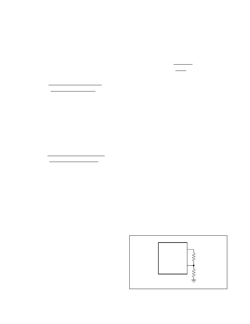
�OUT�
�3.3V� and� 15V.� Connect� a� resistive� divider� between� OUT,�
�FB,� and� GND� to� set� the� output� to� the� desired� voltage,� as�
�shown� in� Figure� 7.� Connect� FB� to� REG� to� configure� the�
�MAX16946� as� an� 8.5V� LDO,� as� shown� in� Figure� 8.� FB� is�
�regulated� to� 1.0V� with� Q� 3%� accuracy� for� a� load� current�
�between� 5mA� and� 150mA.� The� accuracy� falls� to� Q� 5%� for�
�a� load� current� between� 2mA� and� 200mA.� Select� a� value�
�MAX16946�
�FB�
�R� 1�
�R� 2�
�for� R� 1� and� calculate� R� 2� as� follows:�
�Maxim� Integrated�
�Figure� 7.� Adjustable� Output-Voltage� Selection�
�17�
�相关PDF资料 |
PDF描述 |
|---|---|
| S1210R-273K | INDUCTOR SHIELDED 27UH SMD |
| CI100505-39NJ | INDUCTOR CHIP 39NH 1005 SMD |
| CI160808-5N6D | INDUCTOR CHIP 5.6NH 1608 SMD |
| CI160808-3N9D | INDUCTOR CHIP 3.9NH 1608 SMD |
| CI160808-2N7D | INDUCTOR CHIP 2.7NH 1608 SMD |
相关代理商/技术参数 |
参数描述 |
|---|---|
| MAX16946GTE/V+ | 功能描述:电源开关 IC - 配电 Remote Antenna Current-Sense RoHS:否 制造商:Exar 输出端数量:1 开启电阻(最大值):85 mOhms 开启时间(最大值):400 us 关闭时间(最大值):20 us 工作电源电压:3.2 V to 6.5 V 电源电流(最大值): 最大工作温度:+ 85 C 安装风格:SMD/SMT 封装 / 箱体:SOT-23-5 |
| MAX16946GTE/V+T | 功能描述:电源开关 IC - 配电 Remote Antenna Current-Sense RoHS:否 制造商:Exar 输出端数量:1 开启电阻(最大值):85 mOhms 开启时间(最大值):400 us 关闭时间(最大值):20 us 工作电源电压:3.2 V to 6.5 V 电源电流(最大值): 最大工作温度:+ 85 C 安装风格:SMD/SMT 封装 / 箱体:SOT-23-5 |
| MAX16946GUE/V+ | 功能描述:电源开关 IC - 配电 Remote Antenna Current-Sense RoHS:否 制造商:Exar 输出端数量:1 开启电阻(最大值):85 mOhms 开启时间(最大值):400 us 关闭时间(最大值):20 us 工作电源电压:3.2 V to 6.5 V 电源电流(最大值): 最大工作温度:+ 85 C 安装风格:SMD/SMT 封装 / 箱体:SOT-23-5 |
| MAX16946GUE/V+T | 功能描述:电源开关 IC - 配电 Remote Antenna Current-Sense RoHS:否 制造商:Exar 输出端数量:1 开启电阻(最大值):85 mOhms 开启时间(最大值):400 us 关闭时间(最大值):20 us 工作电源电压:3.2 V to 6.5 V 电源电流(最大值): 最大工作温度:+ 85 C 安装风格:SMD/SMT 封装 / 箱体:SOT-23-5 |
| MAX16947GEE/V+ | 功能描述:电源开关 IC - 配电 Remote Antenna Current-Sense RoHS:否 制造商:Exar 输出端数量:1 开启电阻(最大值):85 mOhms 开启时间(最大值):400 us 关闭时间(最大值):20 us 工作电源电压:3.2 V to 6.5 V 电源电流(最大值): 最大工作温度:+ 85 C 安装风格:SMD/SMT 封装 / 箱体:SOT-23-5 |
发布紧急采购,3分钟左右您将得到回复。