- 您现在的位置:买卖IC网 > PDF目录383332 > MAX1700EEE (MAXIM INTEGRATED PRODUCTS INC) 1-Cell to 3-Cell, High-Power 1A, Low-Noise, Step-Up DC-DC Converters PDF资料下载
参数资料
| 型号: | MAX1700EEE |
| 厂商: | MAXIM INTEGRATED PRODUCTS INC |
| 元件分类: | 稳压器 |
| 英文描述: | 1-Cell to 3-Cell, High-Power 1A, Low-Noise, Step-Up DC-DC Converters |
| 中文描述: | 1.8 A SWITCHING REGULATOR, 340 kHz SWITCHING FREQ-MAX, PDSO16 |
| 封装: | 0.150 INCH, 0.025 INCH PITCH, QSOP-16 |
| 文件页数: | 11/16页 |
| 文件大小: | 248K |
| 代理商: | MAX1700EEE |
Synchronized PWM Operation
By applying an external clock to C LK/SEL, the
MAX1700/MAX1701 can also be synchronized in PWM
mode to a frequency between 200kHz and 400kHz.
This allows the user to set the harmonics to avoid IF
bands in wireless applications. The synchronous rectifi-
er is also active during synchronized PWM operation.
Low-Power PFM Operation
Pulling CLK/SEL low places the MAX1700/MAX1701 in
a low-power mode. During low-power mode, PFM oper-
ation regulates the output voltage by transferring a
fixed amount of energy during each cycle and then
modulating the switching frequency to control the
power delivered to the output. The devices switch only
as needed to service the load, resulting in the highest
possible efficiency at light loads. Output current capa-
bility in PFM mode is 100mA. The output voltage is typi-
cally 1% higher than the output voltage in PWM mode.
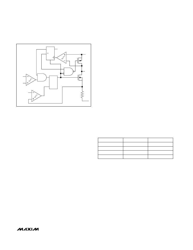
During PFM operation, the error comparator detects the
output voltage falling out of regulation and sets a flip-
flop, turning on the N-channel MOSFET switch (Figure
4). When the inductor current ramps to the PFM mode
current limit (400mA typical) and stores a fixed amount
of energy, the current-sense comparator resets a flip-
flop. The flip-flop turns off the N-channel switch and
turns on the P-channel synchronous rectifier. A second
flip-flop, previously reset by the switch’s “on” signal,
inhibits the error comparator from initiating another
cycle until the energy stored in the inductor is trans-
ferred to the output filter capacitor and the synchronous
rectifier current has ramped down to 70mA. This forces
operation with a discontinuous inductor current.
Synchronous Rectifier
The MAX1700/MAX1701 feature an internal 250m
, P-
channel synchronous rectifier to enhance efficiency.
Synchronous rectification provides a 5% efficiency
improvement over similar nonsynchronous boost regu-
lators. In PWM mode, the synchronous rectifier is
turned on during the second half of each switching
cycle. In low-power mode, an internal comparator turns
on the synchronous rectifier when the voltage at LX
exceeds the boost-regulator output and then turns it off
when the inductor current drops below 70mA.
Low-V oltage S tart-Up Osc illator
The MAX1700/MAX1701 use a CMOS, low-voltage
start-up oscillator for a 1.1V guaranteed minimum start-
up input voltage at +25°C. On start-up, the low-voltage
oscillator switches the N-channel MOSFET until the out-
put voltage reaches 2.15V. Above this level, the normal
boost-converter feedback and control circuitry take
over. Once the device is in regulation, it can operate
down to a 0.7V input since internal power for the IC is
bootstrapped from the output using the OUT pin. Do
not apply full load until the output exceeds 2.4V.
S hutdown
The MAX1700/MAX1701 shut down to reduce quies-
cent current to typically 3μA. During shutdown, the ref-
erence, low-battery comparator, gain block, and all
feedback and control circuitry are off. The boost con-
verter’s output drops to one Schottky diode drop below
the input.
Table 3 shows the control logic with ONA and
ONB
.
Both inputs have trip points near 0.5V
OUT
with
0.15V
OUT
hysteresis.
Low-Battery Comparator (MAX 1701)
The internal low-battery comparator has uncommitted
inputs and an open-drain output (LBO) capable of sink-
ing 1mA. To use it as a low-battery-detection compara-
tor, connect the LBN input to the reference, and
connect the LBP input to an external resistor divider
M
1-Cell to 3-Cell, High-Power (1A),
Low-Noise, S tep-Up DC-DC Converters
______________________________________________________________________________________
11
N
LX
PGND
FB
REF
400mA
CURRENT
LIMIT
ERROR
COMPARATOR
S
Q
R
Q
Q
R
D
LOGIC HIGH
POUT
P
Figure 4. Controller Block Diagram in Low-Power PFM Mode
ONA
0
0
1
1
ONB
0
1
0
1
Status
On
Off
On
On
Table 3. On/Off Logic Control
相关PDF资料 |
PDF描述 |
|---|---|
| MAX1701EEE | 18-Bit Universal Bus Transceivers With 3-State Outputs 56-SSOP -40 to 85 |
| MAX1702B | Triple-Output Power-Management IC for Microprocessor-Based Systems |
| MAX1702BEGX | Triple-Output Power-Management IC for Microprocessor-Based Systems |
| MAX1703 | 1-Cell to 3-Cell, High-Power 1.5A, Low-Noise, Step-Up DC-DC Converter |
| MAX1703ESE | 1-Cell to 3-Cell, High-Power 1.5A, Low-Noise, Step-Up DC-DC Converter |
相关代理商/技术参数 |
参数描述 |
|---|---|
| MAX1700EEE+ | 功能描述:直流/直流开关转换器 1-3 Cell 1A Step-Up DC/DC Converters RoHS:否 制造商:STMicroelectronics 最大输入电压:4.5 V 开关频率:1.5 MHz 输出电压:4.6 V 输出电流:250 mA 输出端数量:2 最大工作温度:+ 85 C 安装风格:SMD/SMT |
| MAX1700EEE+T | 功能描述:直流/直流开关转换器 1-3 Cell 1A Step-Up DC/DC Converters RoHS:否 制造商:STMicroelectronics 最大输入电压:4.5 V 开关频率:1.5 MHz 输出电压:4.6 V 输出电流:250 mA 输出端数量:2 最大工作温度:+ 85 C 安装风格:SMD/SMT |
| MAX1700EEE-T | 功能描述:直流/直流开关转换器 1-3 Cell 1A Step-Up DC/DC Converters RoHS:否 制造商:STMicroelectronics 最大输入电压:4.5 V 开关频率:1.5 MHz 输出电压:4.6 V 输出电流:250 mA 输出端数量:2 最大工作温度:+ 85 C 安装风格:SMD/SMT |
| MAX17010AETL+ | 功能描述:LCD 驱动器 Internal-Switch Boost Regulator RoHS:否 制造商:Maxim Integrated 数位数量:4.5 片段数量:30 最大时钟频率:19 KHz 工作电源电压:3 V to 3.6 V 最大工作温度:+ 85 C 最小工作温度:- 20 C 封装 / 箱体:PDIP-40 封装:Tube |
| MAX17010AETL+T | 功能描述:LCD 驱动器 Internal-Switch Boost Regulator RoHS:否 制造商:Maxim Integrated 数位数量:4.5 片段数量:30 最大时钟频率:19 KHz 工作电源电压:3 V to 3.6 V 最大工作温度:+ 85 C 最小工作温度:- 20 C 封装 / 箱体:PDIP-40 封装:Tube |
发布紧急采购,3分钟左右您将得到回复。