- 您现在的位置:买卖IC网 > PDF目录383332 > MAX1706D (Maxim Integrated Products, Inc.) BALUN HYBRID 750-950MHZ 1:4 PDF资料下载
参数资料
| 型号: | MAX1706D |
| 厂商: | Maxim Integrated Products, Inc. |
| 英文描述: | BALUN HYBRID 750-950MHZ 1:4 |
| 中文描述: | 1 - 3节电池,大电流,低噪声,升压型DC - DC转换器与线性稳压器 |
| 文件页数: | 13/20页 |
| 文件大小: | 215K |
| 代理商: | MAX1706D |
M
1- to 3-Cell, High-Current, Low-Noise,
Step-Up DC-DC Converters with Linear Regulator
______________________________________________________________________________________
13
The linear regulator in the MAX1705/MAX1706 features
a 0.5
, P-channel MOSFET pass transistor. This pro-
vides several advantages, including longer battery life,
over similar designs using a PNP pass transistor. The
P-channel MOSFET requires no base-drive current,
which reduces quiescent current considerably. PNP-
based regulators tend to waste base-drive current in
dropout when the pass transistor saturates. The
MAX1705/MAX1706 eliminate this problem.
The linear-regulator error amplifier compares the output
feedback sensed at the FBLDO input against the inter-
nal 1.250V reference, and amplifies the difference
(Figure 1). The MOSFET driver reads the error signal
and applies the appropriate drive to the P-channel
pass transistor. If the feedback signal is lower than the
reference, the pass-transistor gate is pulled lower,
allowing more current to pass to the output, thereby
increasing the output voltage. If the feedback voltage is
too high, the pass-transistor gate is pulled up, allowing
less current to pass to the output. Additional blocks
include a current-limiting block and a thermal-overload
protection block.
Low-V oltage S tart-Up Osc illator
The MAX1705/MAX1706 use a CMOS, low-voltage
start-up oscillator for a 1.1V guaranteed minimum start-
up input voltage at +25°C. On start-up, the low-voltage
oscillator switches the N-channel MOSFET until the out-
put voltage reaches 2.15V. Above this level, the normal
step-up converter feedback and control circuitry take
over. Once the device is in regulation, it can operate
down to a 0.7V input, since internal power for the IC is
bootstrapped from the output using the OUT pin.
To reduce current loading during step-up, the linear
regulator is kept off until the start-up converter goes
into regulation. Minimum start-up voltage is influenced
by load and temperature (see the Typical Operating
Characteristics). To allow proper start-up, do not apply
a full load at POUT until after the device has exited
start-up mode and entered normal operation.
S hutdown
The MAX1705/MAX1706 feature a shutdown mode that
reduces quiescent current to less than 1μA, preserving
battery life when the system is not in use. During shut-
down, the reference, the low-battery comparator, and
all feedback and control circuitry are off. The step-up
converter’s output drops to one Schottky diode drop
below the input, but the linear regulator output is
turned off.
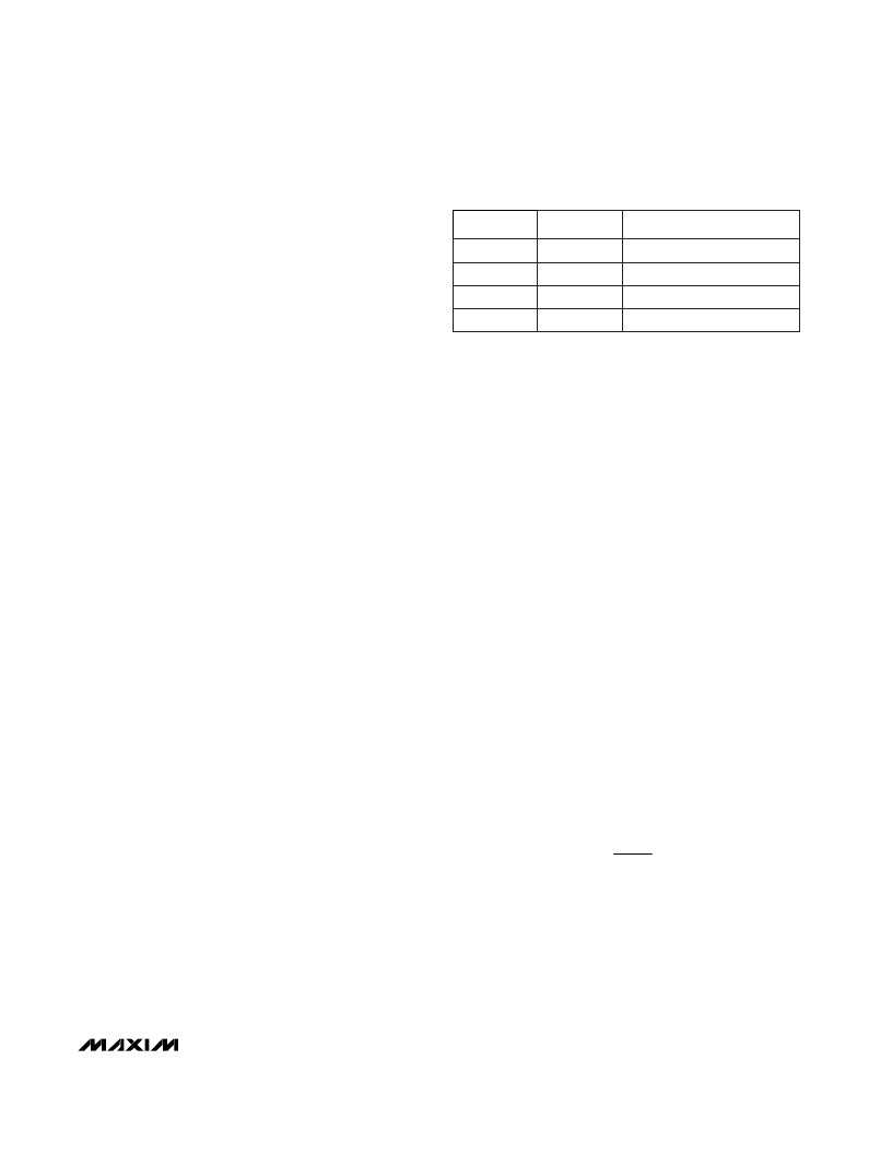
Entry into shutdown mode is controlled by logic input
pins ONA and
ONB
(Table 2). Both inputs have trip
points near 0.5V
OUT
with 0.15V
OUT
hysteresis.
T rac king
Connecting TRACK to the step-up converter output
implements a tracking mode that sets the step-up
converter output to 300mV above the linear-regulator
output, improving efficiency. In track mode, feedback
for the step-up converter is derived from the OUT pin.
When TRACK is low, the step-up converter and linear
regulator are separately controlled by their respective
feedback inputs, FB and FBLDO. TRACK is a logic
input with a 0.5V
OUT
threshold, and should be hard-
wired or switched with a slew rate exceeding 1V/μs.
V
LDO
must be set above 2.3V for track mode to operate
properly.
On power-up with TRACK = OUT, the step-up convert-
er initially uses the FB input to regulate its output. After
the step-up converter goes into regulation for the first
time, the linear regulator turns on. When the linear regu-
lator reaches 2.3V, track mode is enabled and the step-
up converter is regulated to 300mV above the linear-
regulator output.
Low-Battery Comparator
The internal low-battery comparator has uncommitted
inputs and an open-drain output capable of sinking
1mA. To use it as a low-battery-detection comparator,
connect the LBN input to the reference, and connect
the LBP input to an external resistor divider between
the positive battery terminal and GND (Figure 2). The
resistor values are then as follows:
where V
IN,TH
is the desired input voltage trip point and
V
LBN
= V
REF
= 1.25V. Since the input bias current into
LBP is less than 50nA, R6 can be a large value (such
as 270k
or less) without sacrificing accuracy.
Connect the resistor voltage divider as close to the IC
as possible, within 0.2in. (5mm) of the LBP pin. The
inputs have a 0.5V to 1.5V common-mode input range,
and a 16mV input-referred hysteresis.
R
R
V
V
INTH
,
LBN
5
6
=
- 1
ONA
ONB
MAX1705/MAX1706
0
0
On
0
1
Off
1
0
On
1
1
On
Table 2. On/Off Logic Control
相关PDF资料 |
PDF描述 |
|---|---|
| MAX1705C | 1- to 3-Cell, High-Current, Low-Noise, Step-Up DC-DC Converters with Linear Regulator |
| MAX1705D | 1- to 3-Cell, High-Current, Low-Noise, Step-Up DC-DC Converters with Linear Regulator |
| MAX1705EEE | 18-Bit Universal Bus Transceivers With 3-State Outputs 56-SSOP -40 to 85 |
| MAX1706 | 1- to 3-Cell, High-Current, Low-Noise, Step-Up DC-DC Converters with Linear Regulator |
| MAX1706EEE | 1- to 3-Cell, High-Current, Low-Noise, Step-Up DC-DC Converters with Linear Regulator |
相关代理商/技术参数 |
参数描述 |
|---|---|
| MAX1706EEE | 功能描述:直流/直流开关转换器 1-3 Cell Step-Up w/Linear Regulator RoHS:否 制造商:STMicroelectronics 最大输入电压:4.5 V 开关频率:1.5 MHz 输出电压:4.6 V 输出电流:250 mA 输出端数量:2 最大工作温度:+ 85 C 安装风格:SMD/SMT |
| MAX1706EEE+ | 功能描述:直流/直流开关转换器 1-3 Cell Step-Up w/Linear Regulator RoHS:否 制造商:STMicroelectronics 最大输入电压:4.5 V 开关频率:1.5 MHz 输出电压:4.6 V 输出电流:250 mA 输出端数量:2 最大工作温度:+ 85 C 安装风格:SMD/SMT |
| MAX1706EEE+T | 功能描述:直流/直流开关转换器 1-3 Cell Step-Up w/Linear Regulator RoHS:否 制造商:STMicroelectronics 最大输入电压:4.5 V 开关频率:1.5 MHz 输出电压:4.6 V 输出电流:250 mA 输出端数量:2 最大工作温度:+ 85 C 安装风格:SMD/SMT |
| MAX1706EEE-T | 功能描述:直流/直流开关转换器 1-3 Cell Step-Up w/Linear Regulator RoHS:否 制造商:STMicroelectronics 最大输入电压:4.5 V 开关频率:1.5 MHz 输出电压:4.6 V 输出电流:250 mA 输出端数量:2 最大工作温度:+ 85 C 安装风格:SMD/SMT |
| MAX17073ETJ+ | 功能描述:直流/直流开关转换器 TFT-LCD Step-Up DC/DC Converter RoHS:否 制造商:STMicroelectronics 最大输入电压:4.5 V 开关频率:1.5 MHz 输出电压:4.6 V 输出电流:250 mA 输出端数量:2 最大工作温度:+ 85 C 安装风格:SMD/SMT |
发布紧急采购,3分钟左右您将得到回复。