- 您现在的位置:买卖IC网 > PDF目录13258 > MAX1706EEE+ (Maxim Integrated Products)IC REG BOOST ADJ 0.4A 16QSOP PDF资料下载
参数资料
| 型号: | MAX1706EEE+ |
| 厂商: | Maxim Integrated Products |
| 文件页数: | 12/18页 |
| 文件大小: | 0K |
| 描述: | IC REG BOOST ADJ 0.4A 16QSOP |
| 产品培训模块: | Lead (SnPb) Finish for COTS Obsolescence Mitigation Program |
| 标准包装: | 100 |
| 类型: | 升压(升压) |
| 输出类型: | 可调式 |
| 输出数: | 1 |
| 输出电压: | 2.5 V ~ 5.5 V |
| 输入电压: | 0.7 V ~ 5.5 V |
| 频率 - 开关: | 260kHz ~ 340kHz |
| 电流 - 输出: | 400mA |
| 同步整流器: | 无 |
| 工作温度: | -40°C ~ 85°C |
| 安装类型: | 表面贴装 |
| 封装/外壳: | 16-SSOP(0.154",3.90mm 宽) |
| 包装: | 管件 |
| 供应商设备封装: | 16-QSOP |
| 产品目录页面: | 1410 (CN2011-ZH PDF) |
�� �
�
�1-� to� 3-Cell,� High-Current,� Low-Noise,�
�Step-Up� DC-DC� Converters� with� Linear� Regulator�
�POUT�
�Q�
�D�
�LOGIC� HIGH�
�IFB*�
�P�
�Q�
�POUT�
�IREF*�
�R�
�Q�
�LX�
�R�
�P�
�S�
�N�
�LX�
�ICS�
�IFB*�
�S�
�Q�
�N�
�IREF*�
�CURRENT-�
�LIMIT� LEVEL�
�OSC�
�PGND�
�CURRENT-�
�LIMIT� LEVEL�
�R�
�PGND�
�*SEE� FIGURE� 1�
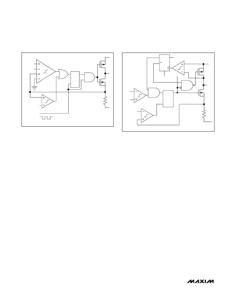
�Figure� 3.� Simplified� PWM� Controller� Block� Diagram�
�current� limit� for� the� MAX1705,� and� 950mA� (max)� for� the�
�MAX1706.� During� PWM� operation,� the� circuit� operates�
�with� a� continuous� inductor� current.�
�Synchronized� PWM� Operation�
�The� MAX1705/MAX1706� can� also� be� synchronized� to� a�
�200kHz� to� 400kHz� frequency� by� applying� an� external�
�clock� to� CLK/SEL.� This� allows� the� user� to� set� the� har-�
�monics,� to� avoid� IF� bands� in� wireless� applications.� The�
�synchronous� rectifier� is� also� active� during� synchronized�
�PWM� operation.�
�Low-Power� PFM� Operation�
�Pulling� CLK/SEL� low� places� the� MAX1705/MAX1706� in�
�low-power� standby� mode.� During� standby� mode,� PFM�
�operation� regulates� the� output� voltage� by� transferring� a�
�fixed� amount� of� energy� during� each� cycle,� and� then�
�modulating� the� switching� frequency� to� control� the�
�power� delivered� to� the� output.� The� devices� switch� only�
�as� needed� to� service� the� load,� resulting� in� the� highest�
�possible� efficiency� at� light� loads.� Output� current� capa-�
�bility� in� PFM� mode� is� 140mA� (from� 2.4V� input� to� 3.3V�
�output).� The� output� is� regulated� at� 1.3%� above� the�
�PWM� threshold.�
�During� PFM� operation,� the� error� comparator� detects�
�output� voltage� falling� out� of� regulation� and� sets� a�
�flip-flop,� turning� on� the� n-channel� MOSFET� switch�
�(Figure� 4).� When� the� inductor� current� ramps� to� the� PFM�
�mode� current� limit� (435mA)� and� stores� a� fixed� amount�
�of� energy,� the� current-sense� comparator� resets� a� flip-�
�flop.� The� flip-flop� turns� off� the� n-channel� switch� and�
�turns� on� the� p-channel� synchronous� rectifier.� A� second�
�flip-flop,� previously� reset� by� the� switch’s� “on”� signal,�
�inhibits� the� error� comparator� from� initiating� another�
�*SEE� FIGURE� 1�
�Figure� 4.� Controller� Block� Diagram� in� PFM� Mode�
�cycle� until� the� energy� stored� in� the� inductor� is� dumped�
�into� the� output� filter� capacitor� and� the� synchronous� rec-�
�tifier� current� ramps� down� to� 70mA.� This� forces� opera-�
�tion� with� a� discontinuous� inductor� current.�
�Synchronous� Rectifier�
�The� MAX1705/MAX1706� feature� an� internal� 270m� ?� ,�
�p-channel� synchronous� rectifier� to� enhance� efficiency.�
�Synchronous� rectification� provides� a� 5%� efficiency�
�improvement� over� similar� nonsynchronous� step-up�
�regulators.� In� PWM� mode,� the� synchronous� rectifier� is�
�turned� on� during� the� second� half� of� each� cycle.� In� PFM�
�mode,� an� internal� comparator� turns� on� the� synchronous�
�rectifier� when� the� voltage� at� LX� exceeds� the� step-up�
�converter� output,� and� then� turns� it� off� when� the� inductor�
�current� drops� below� 70mA.�
�Linear� Regulator�
�The� internal� low-dropout� linear� regulator� steps� down� the�
�output� from� the� step-up� converter� and� reduces� switching�
�ripple.� It� is� intended� to� power� noise-sensitive� analog� cir-�
�cuitry,� such� as� low-noise� amplifiers� and� IF� stages� in� cel-�
�lular� phones� and� other� instruments,� and� can� deliver� up� to�
�200mA.� However,� in� practice,� the� maximum� output� cur-�
�rent� is� further� limited� by� the� current� available� from� the�
�boost� converter� and� by� the� voltage� differential� between�
�OUT� and� LDO.� Use� a� 22μF� capacitor� with� a� 1� ?� or� less�
�equivalent� series� resistance� (ESR)� at� the� output� for� sta-�
�bility� (see� the� Linear� Regulator� Region� of� Stable� C6� ESR�
�vs.� Load� Current� graph� in� the� Typical� Operating�
�Characteristics� ).� When� the� MAX1705/1706� are� activated�
�by� logic� control� (ONA,� ONB� ),� the� linear� regulator� (LDO)�
�remains� off� until� the� step-up� converter� (POUT)� goes� into�
�12�
�______________________________________________________________________________________�
�相关PDF资料 |
PDF描述 |
|---|---|
| HSC22DREF-S13 | CONN EDGECARD 44POS .100 EXTEND |
| MAX1706EEE | IC REG BOOST ADJ 0.4A 16QSOP |
| GMM22DTKN-S288 | CONN EDGECARD 44POS .156 EXTEND |
| HMC22DREF-S13 | CONN EDGECARD 44POS .100 EXTEND |
| MAX1705EEE | IC REG BOOST ADJ 0.85A 16QSOP |
相关代理商/技术参数 |
参数描述 |
|---|---|
| MAX1706EEE+ | 功能描述:直流/直流开关转换器 1-3 Cell Step-Up w/Linear Regulator RoHS:否 制造商:STMicroelectronics 最大输入电压:4.5 V 开关频率:1.5 MHz 输出电压:4.6 V 输出电流:250 mA 输出端数量:2 最大工作温度:+ 85 C 安装风格:SMD/SMT |
| MAX1706EEE+T | 功能描述:直流/直流开关转换器 1-3 Cell Step-Up w/Linear Regulator RoHS:否 制造商:STMicroelectronics 最大输入电压:4.5 V 开关频率:1.5 MHz 输出电压:4.6 V 输出电流:250 mA 输出端数量:2 最大工作温度:+ 85 C 安装风格:SMD/SMT |
| MAX1706EEE-T | 功能描述:直流/直流开关转换器 1-3 Cell Step-Up w/Linear Regulator RoHS:否 制造商:STMicroelectronics 最大输入电压:4.5 V 开关频率:1.5 MHz 输出电压:4.6 V 输出电流:250 mA 输出端数量:2 最大工作温度:+ 85 C 安装风格:SMD/SMT |
| MAX17073ETJ+ | 功能描述:直流/直流开关转换器 TFT-LCD Step-Up DC/DC Converter RoHS:否 制造商:STMicroelectronics 最大输入电压:4.5 V 开关频率:1.5 MHz 输出电压:4.6 V 输出电流:250 mA 输出端数量:2 最大工作温度:+ 85 C 安装风格:SMD/SMT |
| MAX17073ETJ+T | 功能描述:直流/直流开关转换器 TFT-LCD Step-Up DC/DC Converter RoHS:否 制造商:STMicroelectronics 最大输入电压:4.5 V 开关频率:1.5 MHz 输出电压:4.6 V 输出电流:250 mA 输出端数量:2 最大工作温度:+ 85 C 安装风格:SMD/SMT |
发布紧急采购,3分钟左右您将得到回复。