- 您现在的位置:买卖IC网 > PDF目录1839 > MAX1706EEE+T (Maxim Integrated Products)IC REG BOOST ADJ 0.4A 16QSOP PDF资料下载
参数资料
| 型号: | MAX1706EEE+T |
| 厂商: | Maxim Integrated Products |
| 文件页数: | 14/18页 |
| 文件大小: | 0K |
| 描述: | IC REG BOOST ADJ 0.4A 16QSOP |
| 产品培训模块: | Lead (SnPb) Finish for COTS Obsolescence Mitigation Program |
| 标准包装: | 2,500 |
| 类型: | 升压(升压) |
| 输出类型: | 可调式 |
| 输出数: | 1 |
| 输出电压: | 2.5 V ~ 5.5 V |
| 输入电压: | 0.7 V ~ 5.5 V |
| 频率 - 开关: | 260kHz ~ 340kHz |
| 电流 - 输出: | 400mA |
| 同步整流器: | 无 |
| 工作温度: | -40°C ~ 85°C |
| 安装类型: | 表面贴装 |
| 封装/外壳: | 16-SSOP(0.154",3.90mm 宽) |
| 包装: | 带卷 (TR) |
| 供应商设备封装: | 16-QSOP |
�� �
�
�1-� to� 3-Cell,� High-Current,� Low-Noise,�
�Step-Up� DC-DC� Converters� with� Linear� Regulator�
�LBP� is� less� than� 50nA,� R6� can� be� a� large� value� (such�
�as� 270k� ?� or� less)� without� sacrificing� accuracy.�
�Connect� the� resistor� voltage-divider� as� close� to� the� IC�
�as� possible,� within� 0.2in.� (5mm)� of� the� LBP� pin.� The�
�inputs� have� a� 0.5V� to� 1.5V� common-mode� input� range,�
�and� a� 16mV� input-referred� hysteresis.�
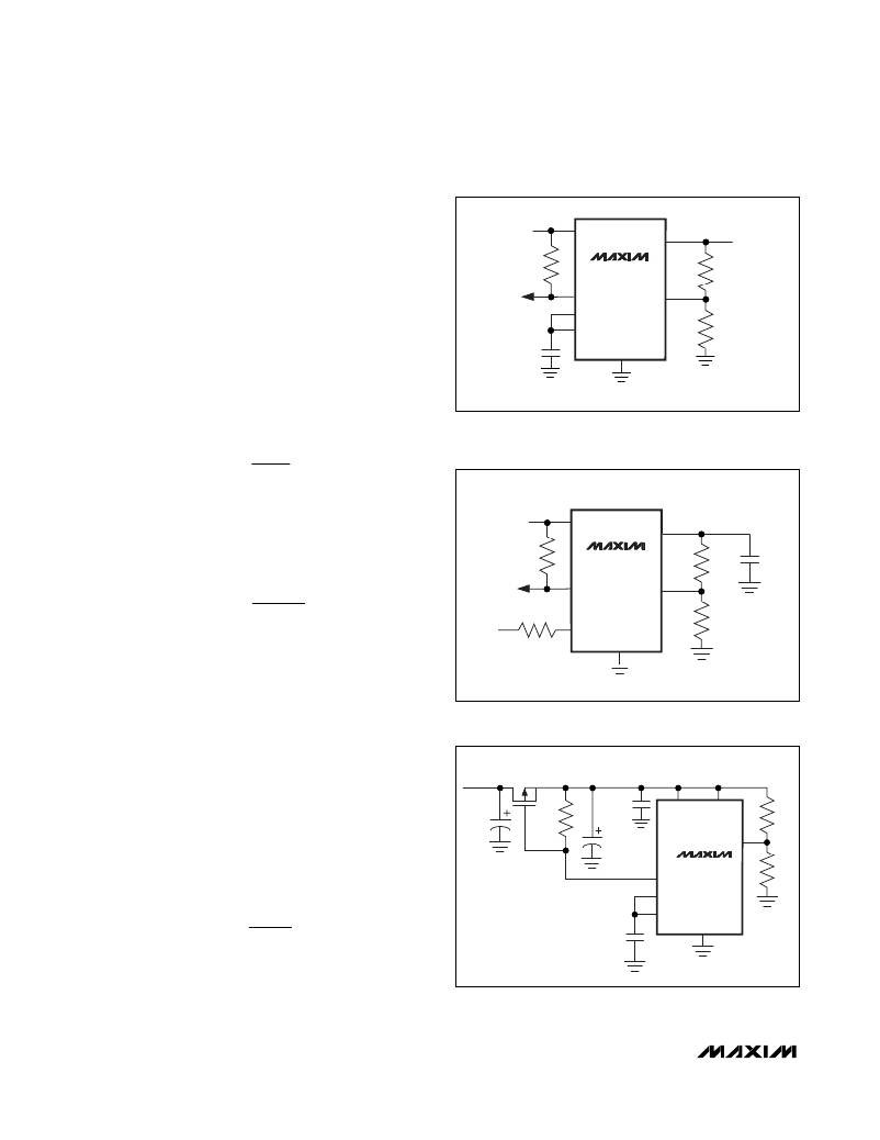
�The� low-battery� comparator� can� also� be� used� to� moni-�
�tor� the� output� voltage,� as� shown� in� Figure� 5.�
�POUT�
�MAX1705�
�MAX1706�
�LBO�
�LBN�
�LDO�
�LBP�
�R5�
�To� set� the� low-battery� threshold� to� a� voltage� below� the�
�1.25V� reference,� insert� a� resistor-divider� between� REF�
�and� LBN,� and� connect� the� battery� to� the� LBP� input�
�through� a� 10k� ?� current-limiting� resistor� (Figure� 6).� The�
�equation� for� setting� the� resistors� for� the� low-battery�
�0.33� μ� F�
�REF�
�GND�
�R6�
�threshold� is� then� as� follows:�
�Figure� 5.� Using� the� Low-Battery� Comparator� to� Sense�
�R� 5� =� R� 6� ?� REF�
�-� 1� ?�
�?� V�
�?� V� IN� ,� TH�
�?�
�?�
�the� Output� Voltage�
�Alternatively,� the� low-battery� comparator� can� be� used�
�to� check� the� output� voltage� or� to� control� the� load� direct-�
�ly� on� POUT� during� startup� (Figure� 7).� Use� the� following�
�POUT�
�REF�
�equation� to� set� the� resistor� values:�
�MAX1705�
�MAX1706�
�R5�
�0.33� μ� F�
�R� 5� =� R� 6� ?�
�-� 1� ?�
�?� V� OUT,TH�
�?� V� LBP�
�?�
�?�
�R8�
�10k� ?�
�LBO�
�LBP�
�LBN�
�R6�
�where� V� OUT,TH� is� the� desired� output� voltage� trip� point�
�and� V� LBP� is� connected� to� the� reference� or� 1.25V.�
�Reference�
�BATTERY�
�VOLTAGE�
�GND�
�The� MAX1705/MAX1706� have� an� internal� 1.250V,� 1%�
�bandgap� reference.� Connect� a� 0.33μF� bypass� capaci-�
�tor� to� GND� within� 0.2in.� (5mm)� of� the� REF� pin.� REF� can�
�source� up� to� 50μA� of� external� load� current.�
�Figure� 6.� Detecting� Battery� Voltages� Below� 1.25V�
�_________________� Design� Procedure�
�P�
�STEP-UP� OUTPUT�
�Setting� the� Output� Voltages�
�Set� the� step-up� converter� output� voltage� between� 2.5V�
�C5�
�270k� ?�
�C3�
�0.1� μ� F�
�OUT�
�POUT�
�R5�
�and� 5.5V� by� connecting� a� resistor� voltage-divider� to� FB�
�from� OUT� to� GND,� as� shown� in� Figure� 8.� The� resistor�
�values� are� then� as� follows:�
�C4�
�MAX1705�
�LBO� MAX1706�
�LBP�
�LBN�
�R6�
�R� 1� =� R� 2� ?� POUT� -� 1� ?�
�?� V� ?�
�?� V� FB� ?�
�0.33� μ� F�
�REF�
�GND�
�where� V� FB� ,� the� step-up� regulator� feedback� setpoint,� is�
�1.233V.� Since� the� input� bias� current� into� FB� is� less� than�
�50nA,� R2� can� have� a� large� value� (such� as� 270k� ?� or�
�Figure� 7.� Using� the� Low-Battery� Comparator� for� Load� Control�
�During� Startup�
�14�
�______________________________________________________________________________________�
�相关PDF资料 |
PDF描述 |
|---|---|
| MAX17075ETG+T | IC DC-DC CONV W/CHRG PUMP 24TQFN |
| MAX17080GTL+T | IC CONTROLLER AMD SVI 40-TQFN |
| MAX17083ETG+T | IC REG BUCK ADJ 5A 24TQFN |
| MAX17085GTL+ | IC CHARGER/CTLR/LDO REG 40-TQFN |
| MAX1708EEE+T | IC REG BST 3.3V/5V/ADJ 5A 16QSOP |
相关代理商/技术参数 |
参数描述 |
|---|---|
| MAX17073ETJ+ | 功能描述:直流/直流开关转换器 TFT-LCD Step-Up DC/DC Converter RoHS:否 制造商:STMicroelectronics 最大输入电压:4.5 V 开关频率:1.5 MHz 输出电压:4.6 V 输出电流:250 mA 输出端数量:2 最大工作温度:+ 85 C 安装风格:SMD/SMT |
| MAX17073ETJ+T | 功能描述:直流/直流开关转换器 TFT-LCD Step-Up DC/DC Converter RoHS:否 制造商:STMicroelectronics 最大输入电压:4.5 V 开关频率:1.5 MHz 输出电压:4.6 V 输出电流:250 mA 输出端数量:2 最大工作温度:+ 85 C 安装风格:SMD/SMT |
| MAX17075ETG+ | 功能描述:直流/直流开关转换器 Boost-Regulator w/Charge Pump RoHS:否 制造商:STMicroelectronics 最大输入电压:4.5 V 开关频率:1.5 MHz 输出电压:4.6 V 输出电流:250 mA 输出端数量:2 最大工作温度:+ 85 C 安装风格:SMD/SMT |
| MAX17075ETG+T | 功能描述:直流/直流开关转换器 Boost-Regulator w/Charge Pump RoHS:否 制造商:STMicroelectronics 最大输入电压:4.5 V 开关频率:1.5 MHz 输出电压:4.6 V 输出电流:250 mA 输出端数量:2 最大工作温度:+ 85 C 安装风格:SMD/SMT |
| MAX17075EVKIT+ | 功能描述:电源管理IC开发工具 MAX17075 Eval Kit RoHS:否 制造商:Maxim Integrated 产品:Evaluation Kits 类型:Battery Management 工具用于评估:MAX17710GB 输入电压: 输出电压:1.8 V |
发布紧急采购,3分钟左右您将得到回复。