- 您现在的位置:买卖IC网 > PDF目录383332 > MAX1710EEG (MAXIM INTEGRATED PRODUCTS INC) High-Speed, Digitally Adjusted Step-Down Controllers for Notebook CPUs PDF资料下载
参数资料
| 型号: | MAX1710EEG |
| 厂商: | MAXIM INTEGRATED PRODUCTS INC |
| 元件分类: | 稳压器 |
| 英文描述: | High-Speed, Digitally Adjusted Step-Down Controllers for Notebook CPUs |
| 中文描述: | SWITCHING CONTROLLER, 550 kHz SWITCHING FREQ-MAX, PDSO24 |
| 封装: | 0.150 INCH, 0.025 INCH PITCH, QSOP-24 |
| 文件页数: | 14/28页 |
| 文件大小: | 299K |
| 代理商: | MAX1710EEG |
第1页第2页第3页第4页第5页第6页第7页第8页第9页第10页第11页第12页第13页当前第14页第15页第16页第17页第18页第19页第20页第21页第22页第23页第24页第25页第26页第27页第28页
M
High-S peed, Digitally Adjusted
S tep-Down Controllers for Notebook CPUs
14
______________________________________________________________________________________
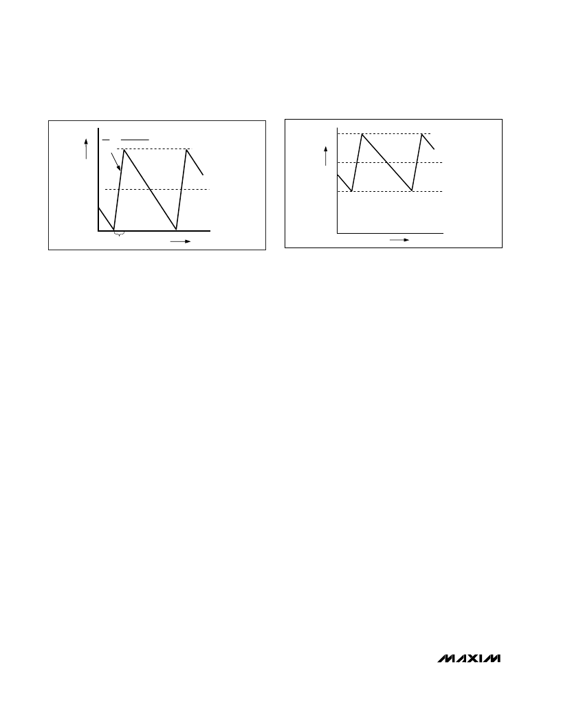
Figure 4. ‘‘Valley’’ Current-Limit Threshold Point
I
I
LIMIT
I
LOAD
0
TIME
LX-PGND I
THRESHOLD = 100mV (NOMINAL, DEFAULT)
VOLTAGE DROP ACROSS Q2
-I
PEAK
about 1/4 full load. The crossover point occurs at an
even lower value if a swinging (soft-saturation) inductor
is used.
The switching waveforms may appear noisy and asyn-
chronous when light loading causes pulse-skipping
operation, but this is a normal operating condition that
results in high light-load efficiency. Trade-offs in PFM
noise vs. light-load efficiency can be made by varying
the inductor value. Generally, low inductor values pro-
duce a broader efficiency vs. load curve, while higher
values result in higher full-load efficiency (assuming that
the coil resistance remains fixed) and less output voltage
ripple. Penalties for using higher inductor values include
larger physical size and degraded load-transient
response (especially at low input voltage levels).
Forced-PWM Mode (
SKIP
= High)
The low-noise, forced-PWM mode (
SKIP
driven high) dis-
ables the zero-crossing comparator, which controls the
low-side switch on-time. This causes the low-side gate-
drive waveform to become the complement of the high-
side gate-drive waveform. This in turn causes the
inductor current to reverse at light loads, as the PWM
loop strives to maintain a duty ratio of V
OUT
/V
IN
. The
benefit of forced-PWM mode is to keep the switching fre-
quency fairly constant, but it comes at a cost: the no-
load battery current can be as high as 40mA or more.
Forced-PWM mode is most useful for reducing audio-fre-
quency noise, improving load-transient response, pro-
viding sink-current capability for dynamic output voltage
adjustment, and improving the cross-regulation of multi-
ple-output applications that use a flyback transformer or
coupled inductor.
Current-Limit Circuit (ILIM)
The current-limit circuit employs a unique “valley” cur-
rent-sensing algorithm that uses the on-state resistance
of the low-side MOSFET as a current-sensing element. If
the current-sense signal is above the current-limit
threshold, the PWM is not allowed to initiate a new cycle
(Figure 4). The actual peak current is greater than the
current-limit threshold by an amount equal to the induc-
tor ripple current. Therefore the exact current-limit char-
acteristic and maximum load capability are a function of
the MOSFET on-resistance, inductor value, and battery
voltage. The reward for this uncertainty is robust, loss-
less overcurrent sensing. When combined with the UVP
protection circuit, this current-limit method is effective in
almost every circumstance.
There is also a negative current limit that prevents exces-
sive reverse inductor currents when V
OUT
is sinking cur-
rent. The negative current-limit threshold is set to
approximately 120% of the positive current limit, and
therefore tracks the positive current limit when ILIM is
adjusted.
The current-limit threshold can be adjusted with an exter-
nal resistor (R
LIM
) at ILIM. A precision 5μA pull-up cur-
rent source at ILIM sets a voltage drop on this resistor,
adjusting the current-limit threshold from 50mV to
200mV. In the adjustable mode, the current-limit thresh-
old voltage is precisely 1/10th the voltage seen at ILIM.
Therefore, choose R
LIM
equal to 2k
/mV of the current-
limit threshold. The threshold defaults to 100mV when
ILIM is tied to V
CC
. The logic threshold for switchover to
the 100mV default value is approximately V
CC
- 1V.
The adjustable current limit can accommodate
MOSFETs with atypical on-resistance characteristics
(see Design Procedure).
A capacitor in parallel with R
LIM
can provide a variable
soft-start function.
Carefully observe the PC board layout guidelines to
ensure that noise and DC errors don’t corrupt the cur-
rent-sense signals seen by LX and PGND. The IC must
be mounted close to the low-side MOSFET with short,
Figure 3. Pulse-Skipping/Discontinuous Crossover Point
I
I
LOAD
= I
PEAK
/2
ON-TIME
0
TIME
-I
PEAK
L
V
BATT
-V
OUT
i
t
=
相关PDF资料 |
PDF描述 |
|---|---|
| MAX1711EEG | High-Speed, Digitally Adjusted Step-Down Controllers for Notebook CPUs |
| MAX1711 | High-Speed, Digitally Adjusted Step-Down Controllers for Notebook CPUs |
| MAX1714 | High-Speed Step-Down Controller for Notebook Computers |
| MAX1714AEEP | High-Speed Step-Down Controller for Notebook Computers |
| MAX1714BEEE | High-Speed Step-Down Controller for Notebook Computers |
相关代理商/技术参数 |
参数描述 |
|---|---|
| MAX1710EEG.TG068 | 制造商:Rochester Electronics LLC 功能描述: 制造商:Maxim Integrated Products 功能描述: |
| MAX1710EEG.TG074 | 制造商:Rochester Electronics LLC 功能描述: 制造商:Maxim Integrated Products 功能描述: |
| MAX1710EEG+ | 制造商:Maxim Integrated Products 功能描述:LDO CNTRLR STDN 1.25V TO 2V 24QSOP - Rail/Tube |
| MAX1710EEG+T | 制造商:Maxim Integrated Products 功能描述:LDO CNTRLR STDN 1.25V TO 2V 24QSOP - Tape and Reel |
| MAX1710EEG-T | 制造商:Rochester Electronics LLC 功能描述: 制造商:Maxim Integrated Products 功能描述: |
发布紧急采购,3分钟左右您将得到回复。