- 您现在的位置:买卖IC网 > PDF目录20744 > MAX1735EUK50-T (Maxim Integrated)IC REG LDO -5V/ADJ .2A SOT23-5 PDF资料下载
参数资料
| 型号: | MAX1735EUK50-T |
| 厂商: | Maxim Integrated |
| 文件页数: | 8/10页 |
| 文件大小: | 0K |
| 描述: | IC REG LDO -5V/ADJ .2A SOT23-5 |
| 产品培训模块: | Lead (SnPb) Finish for COTS Obsolescence Mitigation Program |
| 标准包装: | 2,500 |
| 稳压器拓扑结构: | 负固定式或可调式 |
| 输出电压: | -5V,-1.25 V ~ -5.5 V |
| 输入电压: | -2.5 V ~ -6.5 V |
| 电压 - 压降(标准): | 0.08V @ 200mA |
| 稳压器数量: | 1 |
| 电流 - 输出: | 200mA(最小) |
| 电流 - 限制(最小): | 1.02A |
| 工作温度: | -40°C ~ 85°C |
| 安装类型: | 表面贴装 |
| 封装/外壳: | SC-74A,SOT-753 |
| 供应商设备封装: | SOT-23-5 |
| 包装: | 带卷 (TR) |
�� �
�
�200mA,� Negative-Output,� Low-Dropout�
�Linear� Regulator� in� SOT23�
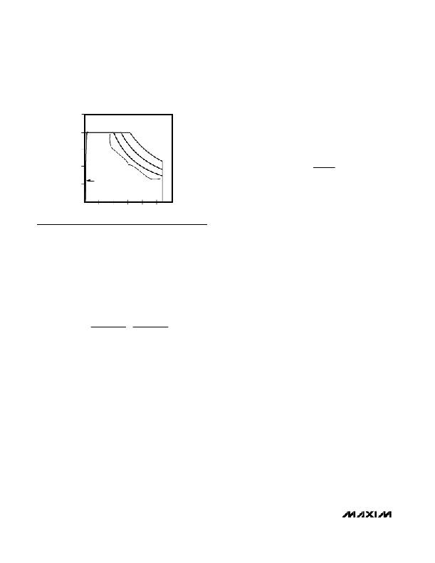
�MAXIMUM� OUTPUT� CURRENT�
�vs.� INPUT-OUTPUT� VOLTAGE� DIFFERENTIAL�
�250�
�selected� ambient� temperatures.� The� working� principle� is�
�that� the� SOT23-5� package� is� small� enough� that� in� a� typi-�
�cal� application� circuit� at� room� temperature,� the� package�
�cannot� dissipate� enough� power� to� allow� -6.5V� to� be� reg-�
�200�
�MAXIMUM� CONTINUOUS� CURRENT�
�ulated� to� -1.25V� at� -200mA� output� (more� than� 1200mW).�
�As� ambient� temperature� falls,� the� available� power� dissi-�
�=+�
�°� C�
�=+�
�°� C�
�=+�
�°� C�
�P� MAX� ?� A�
�|� I� OUT� |� =�
�150�
�100�
�50�
�T� A�
�AT� MAXIMUM�
�JUNCTION� TEMP�
�(T� J� =� +150� °� C)�
�T� A� 50�
�85�
�T� A�
�70�
�pation� increases� to� allow� for� a� greater� operating� region.�
�The� equation� for� the� family� of� curves� follows:�
�T� ?� 70�
�θ� JA�
�|� V� OUT� ?� V� IN� |�
�where� |� I� OUT� |� is� in� mA,� |� V� OUT� -� V� IN� |� in� V,� P� MAX� (571mW)�
�0�
�0�
�1� 2� 3� 4� 5�
�INPUT-OUTPUT� VOLTAGE� DIFFERENTIAL� (V)�
�6�
�is� the� absolute� maximum� rated� power� dissipation� at�
�+70� °� C� for� the� SOT23-5,� and� θ� JA� (0.140� °� C/mW)� is� the�
�approximate� junction-to-ambient� thermal� resistance� of�
�P� MAX� =� JMAX� A� =� JMAX� A�
�Figure� 4.� Output� Current� and� In-Out� Voltage� Differential�
�Operating� Region� Bounded� by� Available� Power� Dissipation� at�
�Selected� Ambient� Temperatures�
�Operating� Region� and� Power� Dissipation�
�Maximum� power� dissipation� of� the� MAX1735� depends�
�on� the� thermal� resistance� of� the� case� and� the� circuit�
�board,� the� temperature� difference� between� the� die�
�junction� and� ambient� air,� and� the� rate� of� air� flow� (see�
�also� Thermal� Overload� Protection� ).� The� maximum�
�power� that� can� be� dissipated� by� the� device� is:�
�T� ?� T� T� ?� T�
�θ� JC� +� θ� CA� θ� JA�
�where� the� numerator� expresses� the� temperature� differ-�
�ence� between� the� maximum� allowed� die� junction�
�(+150� °� C)� and� the� surrounding� air,� θ� JC� (junction� to� case)�
�is� the� thermal� resistance� of� the� package,� and� θ� CA� (case�
�to� ambient)� is� the� thermal� resistance� from� the� package�
�through� the� PC� board,� traces,� and� other� material� to� the�
�surrounding� air.� The� former� is� a� characteristic� solely� of�
�the� device� in� its� package,� and� the� latter� is� completely�
�defined� by� PC� board� layout� and� airflow.� It� is� important� to�
�note� that� the� ability� to� dissipate� power� is� as� much� a� func-�
�tion� of� the� PC� board� layout� and� air� flow� as� the� packaged�
�part� itself.� Hence,� a� manufacturer� can� reliably� provide� a�
�value� for� θ� JC� ,� but� not� accurately� provide� a� value� for� the�
�total� thermal� resistance� θ� JA� .� θ� JA� is� the� sum� of� θ� JC� and�
�θ� CA� ,� and� the� manufacturer� can� seldom� reliably� predict�
�the� thermal� characteristics� of� the� application� circuit.�
�Figure� 4� shows� the� estimated� allowable� power� dissipa-�
�tion� for� a� MAX1735� mounted� on� a� typical� PC� board� at�
�ambient� temperatures� of� +50� °� C,� +70� °� C,� and� +85� °� C.�
�Figure� 4� shows� the� maximum� continuous� output� current�
�for� a� particular� input-to-output� voltage� differential,� for�
�the� SOT23-5� in� a� typical� application.�
�A� key� to� reducing� θ� CA� ,� thereby� increasing� thermal� con-�
�ductivity� to� the� PC� board,� is� to� provide� large� PC� board�
�pads� and� traces� for� IN.�
�__________Applications� Information�
�Capacitor� Selection� and�
�Regulator� Stability�
�Capacitors� are� required� at� the� input� and� output� of� the�
�MAX1735.� Connect� a� 1μF� or� greater� capacitor� between�
�IN� and� GND.� This� input� capacitor� serves� only� to� lower�
�the� source� impedance� of� the� input� supply� in� transient�
�conditions;� a� smaller� value� can� be� used� when� the� regu-�
�lator� is� powered� from� a� low-impedance� source,� such� as�
�another� regulated� supply� or� low-impedance� batteries.�
�For� output� voltages� between� -2.5V� and� -5.5V,� connect�
�a� 1μF� or� greater� capacitor� between� OUT� and� GND.� For�
�voltages� between� -1.25V� and� -2.5V,� use� a� 2.2μF� or�
�greater� output� capacitor.� The� maximum� value� of� the�
�output� capacitor� to� guarantee� stability� is� 10μF.�
�The� output� capacitor� ’� s� value� and� equivalent� series�
�resistance� (ESR)� affect� stability� and� output� noise.� To�
�ensure� stability� and� optimum� transient� response,� output�
�capacitor� ESR� should� be� 0.1� ?� or� less� for� output� volt-�
�ages� from� -1.25V� to� -2.45V� and� 0.2� ?� or� less� for� output�
�voltages� between� -2.5V� and� -5.5V.� Inexpensive� sur-�
�face-mount� ceramic� capacitors� typically� have� very-low�
�ESR� and� are� commonly� available� in� values� up� to� 10μF.�
�Other� low-ESR� capacitors,� such� as� surface-mount� tan-�
�talum,� may� also� be� used.� Do� not� use� low-cost� alu-�
�minum� electrolytic� capacitors� due� to� their� large� size�
�and� relatively� high� ESR.� Lastly,� make� sure� the� input� and�
�output� capacitors� are� as� close� to� the� IC� as� possible� to�
�minimize� the� impact� of� PC� board� trace� impedance.�
�8�
�_______________________________________________________________________________________�
�相关PDF资料 |
PDF描述 |
|---|---|
| GCM06DCMI | CONN EDGECARD 12POS .156 SQ WW |
| GBC25DREH | CONN EDGECARD 50POS .100 EYELET |
| GCM06DCSI | CONN EDGECARD 12POS DIP .156 SLD |
| EEM12DTKI | CONN EDGECARD 24POS DIP .156 SLD |
| GCC12DRAN | CONN EDGECARD 24POS R/A .100 SLD |
相关代理商/技术参数 |
参数描述 |
|---|---|
| MAX1735EUK-C71086 | 制造商:Rochester Electronics LLC 功能描述: 制造商:Maxim Integrated Products 功能描述: |
| MAX1736ETT42+T | 功能描述:电池管理 1Cell Li+ Battery Charger RoHS:否 制造商:Texas Instruments 电池类型:Li-Ion 输出电压:5 V 输出电流:4.5 A 工作电源电压:3.9 V to 17 V 最大工作温度:+ 85 C 最小工作温度:- 40 C 封装 / 箱体:VQFN-24 封装:Reel |
| MAX1736EUT | 制造商:Maxim Integrated Products 功能描述:SOT23 SINGLE-CELL LI+ BATTERY CHAR - Rail/Tube |
| MAX1736EUT+T | 功能描述:电池管理 RoHS:否 制造商:Texas Instruments 电池类型:Li-Ion 输出电压:5 V 输出电流:4.5 A 工作电源电压:3.9 V to 17 V 最大工作温度:+ 85 C 最小工作温度:- 40 C 封装 / 箱体:VQFN-24 封装:Reel |
| MAX1736EUT41 | 制造商:Maxim Integrated Products 功能描述:SOT23 SINGLE-CELL LI+ BATTERY CHAR - Cut Tape Product |
发布紧急采购,3分钟左右您将得到回复。