- 您现在的位置:买卖IC网 > Datasheet目录340 > MAX17410EVKIT+ (Maxim Integrated Products)KIT EVAL FOR MAX17410 CTLR Datasheet资料下载
参数资料
| 型号: | MAX17410EVKIT+ |
| 厂商: | Maxim Integrated Products |
| 文件页数: | 7/20页 |
| 文件大小: | 0K |
| 描述: | KIT EVAL FOR MAX17410 CTLR |
| 产品培训模块: | Lead (SnPb) Finish for COTS Obsolescence Mitigation Program |
| 标准包装: | 1 |
| 系列: | Quick-PWM™ |
| 主要目的: | DC/DC,步降 |
| 输出及类型: | 1,非隔离 |
| 输出电压: | 0 ~ 1.5 V |
| 电流 - 输出: | 38A |
| 输入电压: | 7 ~ 24V |
| 稳压器拓扑结构: | 降压 |
| 频率 - 开关: | 300kHz |
| 板类型: | 完全填充 |
| 已供物品: | 板 |
| 已用 IC / 零件: | MAX17410 |
�� �
�
�MAX17410� Evaluation� Kit�
�Reduced� Power-Dissipation�
�Voltage� Positioning�
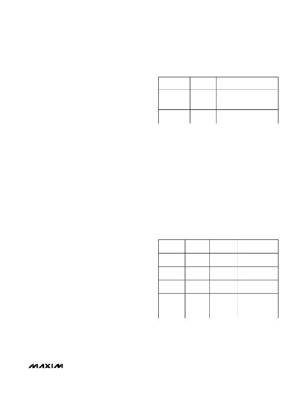
�Table� 3.� Shutdown� Mode� (SHDN)�
�The� MAX17410� includes� a� transconductance� amplifier�
�SW2� (1,� 10)�
�SHDN� PIN�
�MAX17410� OUTPUT�
�for� adding� gain� to� the� voltage-positioning� sense� path.�
�The� amplifier’s� input� is� generated� by� summing� the� cur-�
�rent-sense� inputs,� which� differentially� sense� the� voltage�
�across� the� inductor� ’s� DCR.� The� transconductance�
�amplifier’s� output� connects� to� the� voltage-positioned�
�feedback� input� (FB),� so� the� resistance� between� FB� and�
�VPS� (R4)� determines� the� voltage-positioning� gain.�
�Off�
�On�
�Connected�
�to� VDD�
�Connected�
�to� GND�
�Output� enabled—V� OUT� is�
�selected� by� VID� DAC� code�
�(D0–D6)� settings�
�Shutdown� mode,� V� OUT� =� 0V�
�Resistor� R4� (4.75k� ?� )� provides� a� -2.1mV/A� voltage-posi-�
�tioning� slope� at� the� output� when� all� phases� are� active.�
�Remote� output� and� ground� sensing� eliminate� any� addi-�
�tional� PCB� voltage� drops.�
�Dynamic� Output-Voltage�
�Transition� Experiment�
�This� MAX17410� EV� kit� is� set� to� transition� the� output� volt-�
�age� at� 12.5mV/μs.� The� speed� of� the� transition� is� altered�
�by� scaling� resistors� R2� and� R3.�
�During� the� voltage� transition,� watch� the� inductor� current�
�by� looking� at� the� current-sense� inputs� with� a� differential�
�scope� probe.� Observe� the� low,� well-controlled� inductor�
�current� that� accompanies� the� voltage� transition.� Slew-rate�
�control� during� shutdown� and� startup� results� in� well-con-�
�trolled� currents� in� to� and� out� of� the� battery� (input� source).�
�There� are� two� methods� to� create� an� output-voltage� tran-�
�sition.� Select� D0� –D6� (SW1).� Then� either� manually�
�change� the� SW1� settings� to� a� new� VID� code� setting�
�(Table� 2),� or� disable� all� SW1� settings� and� drive� the�
�VID0–VID6� PCB� test� points� externally� to� the� desired�
�DPRSLPVR� SW2� (2,� 9),� PSI� SW2� (3,� 8)�
�DPRSLPVR� and� PSI� together� determine� the� operating�
�mode,� as� shown� in� Table� 4.� The� MAX17410� will� be�
�forced� into� full-phase� PWM� mode� during� startup,� while�
�in� boot� mode,� during� the� transition� from� boot� mode� to�
�VID� mode,� and� during� shutdown.�
�DPRSTP� SW2� (5,6)�
�The� DPRSTP� logic� signal� is� usually� the� logical� comple-�
�ment� of� the� DPRSLPVR� signal.� However,� there� is� a� spe-�
�cial� condition� when� both� DPRSTP� and� DPRSLPVR�
�could� temporarily� be� simultaneously� high.� If� this� hap-�
�pens,� the� slew� rate� reduces� to� 1/4� of� the� normal� (R� TIME� -�
�based)� slew� rate� for� the� duration� of� this� condition.� The�
�slew� rate� returns� to� normal� when� this� condition� is� exit-�
�ed.� Note:� Only� DPRSLPVR� and� PSI� (� not� DPRSTP� )�
�determine� the� mode� of� operation� (PWM� vs.� skip� and� the�
�number� of� active� phases).� See� Table� 5.�
�Table� 4.� DPRSLPVR,� PSI�
�code� settings.�
�Switch� SW2� Settings�
�Shutdown� SW2� (1,� 10)�
�When� SHDN� goes� low� (SW2� (1,� 10)� =� on),� the�
�MAX17410� enters� the� low-power� shutdown� mode.�
�PWRGD� is� pulled� low� immediately,� and� the� output� volt-�
�age� ramps� down� at� 1/8� the� slew� rate� set� by� R2� and� R3�
�(71.9k� ?� ).� When� the� controller� reaches� the� 0V� target,� the�
�drivers� are� disabled� (DL1� and� DL2� driven� high),� the� ref-�
�erence� is� turned� off,� and� the� IC� supply� currents� drop� to�
�1μA� (max).�
�When� a� fault� condition� activates� the� shutdown�
�DPRSLPVR�
�SW2� (2,� 9)�
�On� (VDD)�
�On� (VDD)�
�Off� (GND)�
�Off� (GND)�
�PSI�
�SW2� (3,� 8)�
�On� (GND)�
�Off� (VDD)�
�On� (GND)�
�Off� (VDD)�
�POWER�
�LEVEL�
�Very� low�
�current�
�Low� current�
�(3A)�
�Intermediate�
�Maximum�
�OPERATING�
�MODE�
�1-phase� pulse-�
�skipping� mode�
�1-phase� pulse-�
�skipping� mode�
�1-phase� forced-�
�PWM� mode�
�Normal�
�operation—all�
�phases� are� active,�
�sequence� (output� undervoltage� lockout� or� thermal� shut-�
�down),� the� protection� circuitry� sets� the� fault� latch� to� pre-�
�vent� the� controller� from� restarting.� To� clear� the� fault�
�latch� and� reactivate� the� MAX17410,� toggle� SHDN� or�
�cycle� VDD� power.� Table� 3� shows� the� shutdown� mode�
�(SHDN).�
�forced-PWM� mode�
�_______________________________________________________________________________________�
�7�
�相关PDF资料 |
PDF描述 |
|---|---|
| MAX17605AUA+ | IC MOSFET DRVR 4A DUAL 8UMAX |
| MAX1848ETA+T | IC LED DRIVR WHITE BCKLGT 8-TDFN |
| MAX1912EUB+ | IC LED DRVR WHITE BCKLGT 10-MSOP |
| MAX1916EZT+T | IC LED DVR WHITE BCKLGT 6TSOT |
| MAX1986ETE+T | IC LED DRVR WHITE BCKLGT 16-TQFN |
相关代理商/技术参数 |
参数描述 |
|---|---|
| MAX17410EVKIT+ | 功能描述:电源管理IC开发工具 MAX17410 Eval Kit RoHS:否 制造商:Maxim Integrated 产品:Evaluation Kits 类型:Battery Management 工具用于评估:MAX17710GB 输入电压: 输出电压:1.8 V |
| MAX17410GTM+ | 功能描述:电流型 PWM 控制器 NDA IC RoHS:否 制造商:Texas Instruments 开关频率:27 KHz 上升时间: 下降时间: 工作电源电压:6 V to 15 V 工作电源电流:1.5 mA 输出端数量:1 最大工作温度:+ 105 C 安装风格:SMD/SMT 封装 / 箱体:TSSOP-14 |
| MAX17410GTM+T | 功能描述:电流型 PWM 控制器 NDA IC RoHS:否 制造商:Texas Instruments 开关频率:27 KHz 上升时间: 下降时间: 工作电源电压:6 V to 15 V 工作电源电流:1.5 mA 输出端数量:1 最大工作温度:+ 105 C 安装风格:SMD/SMT 封装 / 箱体:TSSOP-14 |
| MAX17411GTM+ | 功能描述:电流型 PWM 控制器 IMVP7 CPU & Graphics Controller RoHS:否 制造商:Texas Instruments 开关频率:27 KHz 上升时间: 下降时间: 工作电源电压:6 V to 15 V 工作电源电流:1.5 mA 输出端数量:1 最大工作温度:+ 105 C 安装风格:SMD/SMT 封装 / 箱体:TSSOP-14 |
| MAX17411GTM+T | 功能描述:电流型 PWM 控制器 IMVP7 CPU & Graphics Controller RoHS:否 制造商:Texas Instruments 开关频率:27 KHz 上升时间: 下降时间: 工作电源电压:6 V to 15 V 工作电源电流:1.5 mA 输出端数量:1 最大工作温度:+ 105 C 安装风格:SMD/SMT 封装 / 箱体:TSSOP-14 |
发布紧急采购,3分钟左右您将得到回复。