- 您现在的位置:买卖IC网 > PDF目录15514 > MAX1762EUB+ (Maxim Integrated Products)IC REG CTRLR BUCK PWM CM 10-UMAX PDF资料下载
参数资料
| 型号: | MAX1762EUB+ |
| 厂商: | Maxim Integrated Products |
| 文件页数: | 12/20页 |
| 文件大小: | 0K |
| 描述: | IC REG CTRLR BUCK PWM CM 10-UMAX |
| 产品培训模块: | Lead (SnPb) Finish for COTS Obsolescence Mitigation Program |
| 标准包装: | 50 |
| PWM 型: | 电流模式 |
| 输出数: | 1 |
| 频率 - 最大: | 328kHz |
| 电源电压: | 5 V ~ 20 V |
| 降压: | 是 |
| 升压: | 无 |
| 回扫: | 无 |
| 反相: | 无 |
| 倍增器: | 无 |
| 除法器: | 无 |
| Cuk: | 无 |
| 隔离: | 无 |
| 工作温度: | -40°C ~ 85°C |
| 封装/外壳: | 10-TFSOP,10-MSOP(0.118",3.00mm 宽) |
| 包装: | 管件 |
�� �
�
�High-Efficiency,� 10-Pin� μMAX,� Step-Down�
�Controllers� for� Notebooks�
�(� )�
�2.55� μ� s�
�(� )�
�(� )�
�Overdriving� the� VL� regulator� with� an� external� 5V� supply�
�also� increases� the� MAX1762/MAX1791s’� efficiency.�
�The� MAX1762/MAX1791� include� an� input� undervoltage�
�lockout� (UVLO)� circuit� that� prevents� the� device� from�
�switching� until� VL� >� 4.4V� (max).� UVLO� ensures� there� is�
�a� sufficient� drive� for� the� external� MOSFETs,� prevents�
�the� high-side� MOSFET� from� being� turned� on� for� near�
�100%� duty� cycle,� and� keeps� the� output� in� regulation.�
�Voltage� Reference� (REF)�
�The� 2V� reference� (REF)� is� accurate� to� ±1%� over� tem-�
�perature,� making� REF� useful� as� a� precision� system� ref-�
�erence.� Bypass� REF� to� GND� with� a� 0.1μF� (min)� ceramic�
�capacitor.� REF� can� supply� up� to� 50μA� for� external�
�loads.� However,� if� tight-accuracy� specs� for� either� V� OUT�
�or� REF� are� essential,� avoid� loading� REF.� Loading� slight-�
�ly� reduces� the� main� output� voltage� by� an� amount� that�
�tracks� the� reference-voltage� load� regulation� error.�
�Free-Running� Constant� On-Time� PWM�
�Controller� with� Input� Feed-Forward�
�The� PWM� control� architecture� is� a� quasi-fixed-frequen-�
�cy� constant� on-time� current-mode� type� with� voltage�
�feed-forward.� This� architecture� relies� on� the� output� rip-�
�ple� voltage� to� provide� the� PWM� ramp� signal;� thus,� the�
�adjustable� 0.5μs� (max)� minimum� off-time.� Worst-case�
�dropout� performance� is� determined� by� the� minimum�
�on-time� spec.� The� worst-case� duty� factor� limit� is:�
�t� ON� MIN�
�=� =� 84%�
�t� ON� MIN� +� t� OFF� MAX� 2.55� μ� s+0.5� μ� s�
�with� V� BATT� =� 6V� and� V� OUT� =� 5V.� Therefore,� with� IR� volt-�
�age� drops� in� the� loop� included,� the� minimum� input� volt-�
�age� to� achieve� V� OUT� =� 5V� is� about� 6.1V,� using� the�
�step-down� transfer� function� equation� for� duty� cycle� (DC�
�=� V� OUT� /V� IN� ).� Typical� units� exhibit� better� performance.�
�Note� that� transient� response� is� somewhat� degraded�
�near� dropout,� and� the� circuit� may� need� additional� bulk�
�output� capacitance� to� support� fast� load� changes.�
�Automatic� Pulse-Skipping� Switchover�
�This� PWM� control� algorithm� automatically� switches� over�
�to� pulse-skipping� operation� at� light� loads.� The�
�MAX1762/MAX1791� truncates� the� low-side� switch’s� on-�
�time� when� the� inductor� current� drops� to� zero.� The� load�
�current� level� at� which� pulse-skipping/PWM� crossover�
�occurs� is� equal� to� 1/2� the� peak-to-peak� ripple� current,�
�which� is� a� function� of� the� inductor� value� (Figure� 6):�
�?�
�?�
�?� ?�
�output� filter� capacitor’s� ESR� acts� as� a� feedback� resis-�
�tor.� The� control� algorithm� is� very� simple.� The� high-side�
�switch� on-time� is� determined� solely� by� a� one-shot�
�I� LOAD(SKIP)� =�
�K� � V� OUT�
�2L�
�?� V� VP� -� V� OUT� ?�
�V� VP�
�(� V� OUT� +� 0.075V� )�
�whose� period� is� inversely� proportional� to� input� voltage�
�and� directly� proportional� to� output� voltage.� There� is�
�another� one-shot� that� sets� a� minimum� amount� of� off-�
�time� (500ns� max).� The� on-time� one-shot� triggers� when�
�all� of� the� following� conditions� are� met:� the� error� com-�
�parator� is� low,� the� low-side� switch� current� is� below� the�
�current-limit� threshold,� and� the� minimum� off-time� one-�
�shot� has� timed� out.�
�On-Time� One-Shot�
�The� on-time� of� the� one-shot� is� inversely� proportional� to�
�the� battery� voltage� as� measured� by� the� VP� input,� and�
�directly� proportional� to� the� output� voltage� sensed� at�
�OUT:�
�t� ON� =� K� �
�V� BATT�
�where� K� is� internally� fixed� at� 3.349μs,� and� 0.075V� is� a�
�factor� that� accounts� for� the� expected� drop� across� the�
�The� inductor� current� is� never� allowed� to� go� negative.� If�
�the� output� voltage� is� above� its� regulation� point� and� the�
�inductor� current� reaches� zero,� the� low-side� driver� is�
�switched� off.� Once� the� output� voltage� falls� below� its�
�regulation� point,� the� high-side� driver� is� switched� on.�
�This� causes� a� dead� time� in� between� when� the� high-�
�side� and� low-side� drivers� are� on,� skipping� pulses� and�
�resulting� in� the� switching� frequency� slowing� at� light�
�loads,� thereby� improving� efficiency.�
�MOSFET� Gate� Drivers�
�The� DH� and� DL� drivers� are� optimized� for� driving� moder-�
�ate-size� power� MOSFETs.� This� is� consistent� with� the�
�low� duty� factor� seen� in� the� notebook� CPU� environment�
�where� a� large� V� BATT� -� V� OUT� differential� exists.� The� high-�
�side� driver� (DH)� is� rated� for� 0.6A� source/sink� capability�
�and� swings� from� VP� to� GND.� The� low-side� driver� (DL)� is�
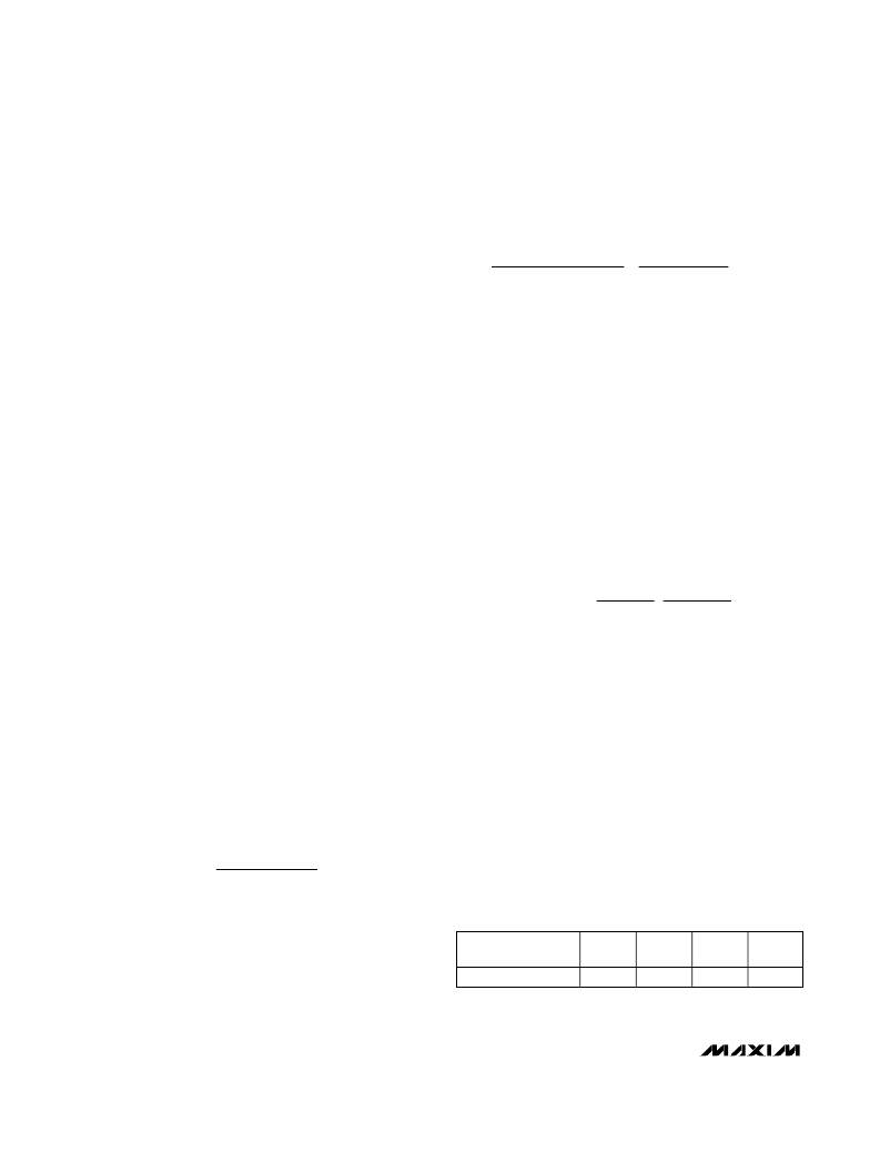
�Table� 3.� Operating� Frequency�
�synchronous� switch.� This� arrangement� maintains� a�
�switching� frequency� that� is� nearly� constant� as� V� BATT� ,�
�I� LOAD� ,� and� V� OUT� are� changed.� Table� 3� shows� the� oper-�
�ating� frequency� range� for� the� MAX1762/MAX1791.�
�DEVICE�
�MAX1762/MAX1791�
�K�
�(� μ� s)�
�3.349�
�MIN�
�(kHz)�
�268.7�
�TYP�
�(kHz)�
�298.5�
�MAX�
�(kHz)�
�328�
�Note� that� the� output� voltage� adjust� range� for� continu-�
�ous-conduction� operation� is� restricted� by� the� non-�
�12�
�______________________________________________________________________________________�
�相关PDF资料 |
PDF描述 |
|---|---|
| MAX1791EUB+ | IC REG CTRLR BUCK PWM CM 10-UMAX |
| MAX775CSA+ | IC REG CTRLR INV PWM 8-SOIC |
| MAX776CSA+ | IC REG CTRLR INV PWM 8-SOIC |
| MAX774CSA+ | IC REG CTRLR INV PWM 8-SOIC |
| MAX669EUB+ | IC REG CTRLR PWM HYBRID 10-UMAX |
相关代理商/技术参数 |
参数描述 |
|---|---|
| MAX1762EUB+ | 功能描述:DC/DC 开关控制器 Step-Down Controller for Notebooks RoHS:否 制造商:Texas Instruments 输入电压:6 V to 100 V 开关频率: 输出电压:1.215 V to 80 V 输出电流:3.5 A 输出端数量:1 最大工作温度:+ 125 C 安装风格: 封装 / 箱体:CPAK |
| MAX1762EUB+T | 功能描述:DC/DC 开关控制器 Step-Down Controller for Notebooks RoHS:否 制造商:Texas Instruments 输入电压:6 V to 100 V 开关频率: 输出电压:1.215 V to 80 V 输出电流:3.5 A 输出端数量:1 最大工作温度:+ 125 C 安装风格: 封装 / 箱体:CPAK |
| MAX1762EUB-T | 功能描述:DC/DC 开关控制器 RoHS:否 制造商:Texas Instruments 输入电压:6 V to 100 V 开关频率: 输出电压:1.215 V to 80 V 输出电流:3.5 A 输出端数量:1 最大工作温度:+ 125 C 安装风格: 封装 / 箱体:CPAK |
| MAX1763EEE | 功能描述:直流/直流开关转换器 1.5A Low-Noise 1MHz Step-Up RoHS:否 制造商:STMicroelectronics 最大输入电压:4.5 V 开关频率:1.5 MHz 输出电压:4.6 V 输出电流:250 mA 输出端数量:2 最大工作温度:+ 85 C 安装风格:SMD/SMT |
| MAX1763EEE+ | 功能描述:直流/直流开关转换器 1.5A Low-Noise 1MHz Step-Up RoHS:否 制造商:STMicroelectronics 最大输入电压:4.5 V 开关频率:1.5 MHz 输出电压:4.6 V 输出电流:250 mA 输出端数量:2 最大工作温度:+ 85 C 安装风格:SMD/SMT |
发布紧急采购,3分钟左右您将得到回复。