- 您现在的位置:买卖IC网 > PDF目录14390 > MAX1763EUE+ (Maxim Integrated Products)IC REG BST SYNC 3.3V/ADJ 16TSSOP PDF资料下载
参数资料
| 型号: | MAX1763EUE+ |
| 厂商: | Maxim Integrated Products |
| 文件页数: | 13/18页 |
| 文件大小: | 0K |
| 描述: | IC REG BST SYNC 3.3V/ADJ 16TSSOP |
| 产品培训模块: | Lead (SnPb) Finish for COTS Obsolescence Mitigation Program |
| 标准包装: | 96 |
| 类型: | 升压(升压) |
| 输出类型: | 两者兼有 |
| 输出数: | 1 |
| 输出电压: | 3.3V,2.5 V ~ 5.5 V |
| 输入电压: | 0.7 V ~ 5.5 V |
| PWM 型: | 混合物 |
| 频率 - 开关: | 750kHz ~ 1.2MHz |
| 电流 - 输出: | 1.5A |
| 同步整流器: | 是 |
| 工作温度: | -40°C ~ 85°C |
| 安装类型: | 表面贴装 |
| 封装/外壳: | 16-TSSOP(0.173",4.40mm)裸露焊盘 |
| 包装: | 管件 |
| 供应商设备封装: | 16-TSSOP-EP |
�� �
�
�1.5A,� Low-Noise,� 1MHz,� Step-Up�
�DC-DC� Converter�
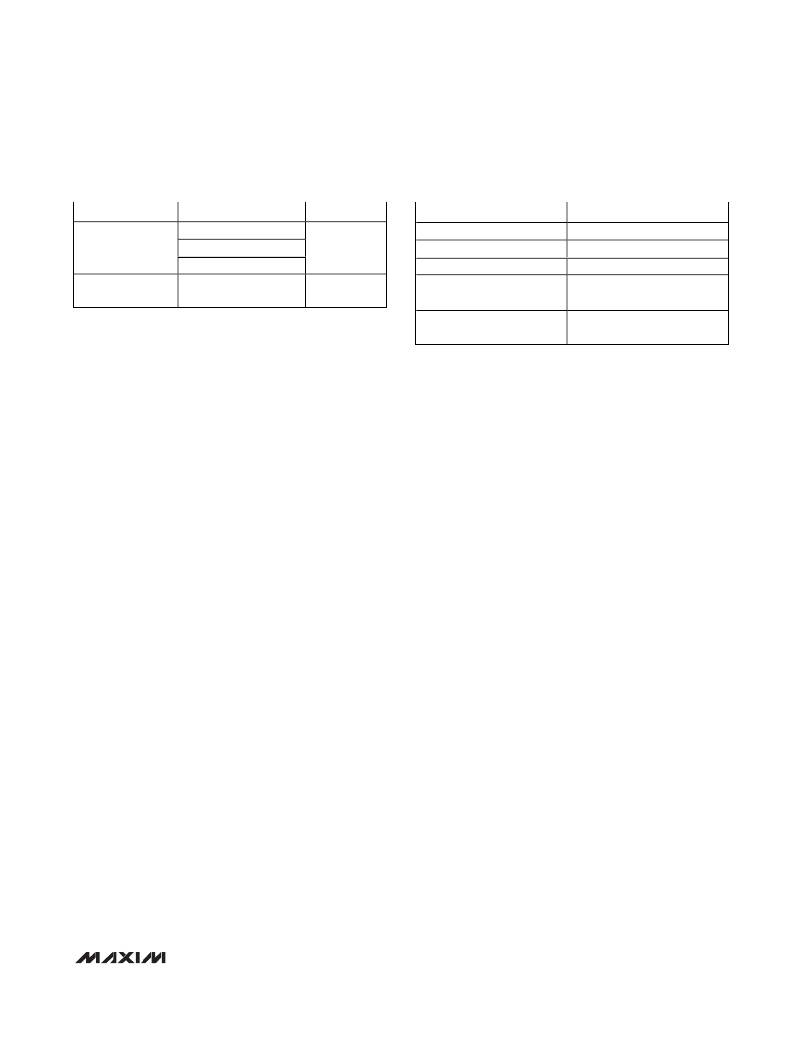
�Table� 4.� Component� Selection� Guide�
�Table� 5.� Component� Suppliers�
�INDUCTORS�
�Coilcraft� LPT3305�
�Sumida�
�CAPACITORS�
�AVX� TPS� series�
�Kemet� T510� series�
�Sanyo� POSCAP� series�
�Panasonic� SP/CB�
�DIODES�
�Motorola�
�MBR0520L�
�Nihon�
�EP10QY03�
�SUPPLIER�
�AVX�
�Coilcraft�
�Kemet�
�Motorola�
�PHONE�
�USA:� 843-448-9411�
�USA:� 847-639-6400�
�USA:� 810-287-2536�
�USA:� 408-629-4789�
�Japan:� 81-45-474-7030�
�At� an� ambient� temperature� of� +70°C,� continuous� power�
�dissipation� for� the� QSSOP� package� is� 667mW,� while�
�Sumida�
�USA:� 847-956-0666�
�Japan:� 011-81-3-3667-3302�
�the� TSSOP-EP� can� dissipate� 1.5W.� A� first-order� esti-�
�mate� of� power� dissipation� can� be� determined� by� calcu-�
�lating� the� output� power� delivered� to� the� load� (e.g.,� 3.3V�
�?� 1A� =� 3.3W).� At� the� input� voltage� used,� find� the� effi-�
�ciency� from� the� Typical� Operating� Characteristics�
�graphs� (e.g.,� 87%).� The� estimated� power� dissipation� in�
�the� MAX1763� is� then:� (100%� -� %Efficiency)� ?� Output�
�Power.� The� example� would� have:� 13%� ?� 3.3W� =� 0.43W,�
�allowing� the� QSOP� package� (667mW)� to� be� used.� For�
�higher� ambient� temperature,� higher� output� power,� or� a�
�lower-efficiency� operating� point,� the� TSSOP-EP� pack-�
�age� (1.5W)� may� be� necessary.� For� detailed� package�
�mechanical� information,� see� the� package� outline� draw-�
�ings� at� the� end� of� this� data� sheet.�
�Inductor� Selection�
�The� MAX1763’s� high� switching� frequency� allows� the�
�use� of� a� small� 1.5μH� surface-mount� inductor.� The� cho-�
�sen� inductor� should� generally� have� a� saturation� current�
�rating� exceeding� the� N-channel� switch� current� limit;�
�however,� it� is� acceptable� to� bias� the� inductor� current�
�into� saturation� by� as� much� as� 20%� if� a� slight� reduction�
�in� efficiency� is� acceptable.� Inductors� rated� for� lower�
�peak� current� may� be� used� if� ISET� is� employed� to�
�reduce� the� peak� inductor� current� (see� Setting� the�
�Switch� Current� Limit� and� Soft-Start� ).� For� high� efficiency,�
�choose� an� inductor� with� a� high-frequency� ferrite� core�
�material� to� reduce� core� losses.� To� minimize� radiated�
�noise,� use� a� toroid� or� shielded� inductor.� See� Table� 4� for�
�suggested� components� and� Table� 5� for� a� list� of� compo-�
�nent� suppliers.� Connect� the� inductor� from� the� battery� to�
�the� LX� pins� as� close� to� the� IC� as� possible.�
�External� Diode�
�For� conditions� where� V� IN� might� exceed� the� set� V� OUT� ,� or�
�where� V� OUT� is� set� above� 4V,� an� external� Schottky� diode�
�must� be� connected� from� LX� to� POUT� in� parallel� with� the�
�on-chip� synchronous� rectifier.� See� D1� in� Figure� 2.� The�
�diode� should� be� rated� for� 0.5A.� Representative� devices�
�are� Motorola� MBR0520L,� Nihon� EP05Q03L,� or� generic�
�1N5817.� This� external� diode� is� also� recommended� for�
�applications� that� must� start� with� input� voltages� at� or�
�Note:� Please� indicate� that� you� are� using� the� MAX1763� when�
�contacting� these� component� suppliers.�
�below� 1.8V.� The� Schottky� diode� carries� current� during�
�both� startup� and� after� the� synchronous� rectifier� turns�
�off.� Thus,� its� current� rating� only� needs� to� be� 500mA�
�even� if� the� inductor� current� is� higher.� Connect� the�
�diode� as� close� to� the� IC� as� possible.� Do� not� use� ordi-�
�nary� rectifier� diodes;� their� slow� switching� speeds� and�
�long� reverse-recovery� times� render� them� unacceptable.�
�For� circuits� that� do� not� require� startup� with� inputs� below�
�1.8V,� and� have� an� output� of� 4V� or� less,� no� external�
�diode� is� needed.�
�Input� and� Output� Capacitors�
�Choose� input� and� output� capacitors� that� will� service� the�
�input� and� output� peak� currents� with� acceptable� voltage�
�ripple.� Choose� input� capacitors� with� working� voltage� rat-�
�ings� over� the� maximum� input� voltage,� and� output� capaci-�
�tors� with� working� voltage� ratings� higher� than� the� output.� A�
�220μF,� low� equivalent-series-resistance� (ESR)� (less� than�
�100m� Ω� )� capacitor� is� recommended� for� most� applica-�
�tions.� Alternatively,� two� 100μF� capacitors� in� parallel� will�
�reduce� the� effective� ESR� for� even� better� performance.�
�The� input� capacitor� reduces� peak� currents� drawn� from�
�the� input� source� and� also� reduces� input� switching� noise.�
�The� input� voltage� source� impedance� determines� the�
�required� size� of� the� input� capacitor.� When� operating�
�directly� from� one� or� two� NiMH� cells� placed� close� to� the�
�MAX1763,� use� a� single� 47μF� low-ESR� input� filter� capac-�
�itor.� With� higher� impedance� batteries,� such� as� alkaline�
�and� Li+,� a� higher� value� input� capacitor� may� improve�
�efficiency.�
�Sanyo� POSCAP,� Panasonic� SP/CB,� and� Kemet� T510�
�are� good� low-ESR� capacitors� (Tables� 4� and� 5).� Low-�
�ESR� tantalum� capacitors� offer� a� good� trade-off� between�
�price� and� performance.� Do� not� exceed� the� ripple� cur-�
�rent� ratings� of� tantalum� capacitors.� Avoid� aluminum�
�electrolytic� capacitors;� their� high� ESR� typically� results�
�in� higher� output� ripple� voltage.�
�______________________________________________________________________________________�
�13�
�相关PDF资料 |
PDF描述 |
|---|---|
| RBM28DRYN | CONN EDGECARD 56POS DIP .156 SLD |
| RCB45DHFN | CONN EDGECARD 90POS .050 SMD |
| RCB45DHFD | CONN EDGECARD 90POS .050 SMD |
| MAX5097BATE+ | IC REG BUCK 5V/ADJ 0.6A 16TQFN |
| GBC70DCST | CONN EDGECARD 140PS DIP .100 SLD |
相关代理商/技术参数 |
参数描述 |
|---|---|
| MAX1763EUE+ | 功能描述:直流/直流开关转换器 1.5A Low-Noise 1MHz Step-Up RoHS:否 制造商:STMicroelectronics 最大输入电压:4.5 V 开关频率:1.5 MHz 输出电压:4.6 V 输出电流:250 mA 输出端数量:2 最大工作温度:+ 85 C 安装风格:SMD/SMT |
| MAX1763EUE+T | 功能描述:直流/直流开关转换器 1.5A Low-Noise 1MHz Step-Up RoHS:否 制造商:STMicroelectronics 最大输入电压:4.5 V 开关频率:1.5 MHz 输出电压:4.6 V 输出电流:250 mA 输出端数量:2 最大工作温度:+ 85 C 安装风格:SMD/SMT |
| MAX1763EUE+TG069 | 制造商:Maxim Integrated Products 功能描述: |
| MAX1763EUE-T | 功能描述:直流/直流开关转换器 1.5A Low-Noise 1MHz Step-Up RoHS:否 制造商:STMicroelectronics 最大输入电压:4.5 V 开关频率:1.5 MHz 输出电压:4.6 V 输出电流:250 mA 输出端数量:2 最大工作温度:+ 85 C 安装风格:SMD/SMT |
| MAX1763EUE-TG068 | 制造商:Maxim Integrated Products 功能描述:16 PINS TSSOP PKG - Tape and Reel |
发布紧急采购,3分钟左右您将得到回复。