- 您现在的位置:买卖IC网 > PDF目录13541 > MAX1776EUA+T (Maxim Integrated Products)IC REG BUCK 5V/ADJ 0.6A 8UMAX PDF资料下载
参数资料
| 型号: | MAX1776EUA+T |
| 厂商: | Maxim Integrated Products |
| 文件页数: | 11/13页 |
| 文件大小: | 0K |
| 描述: | IC REG BUCK 5V/ADJ 0.6A 8UMAX |
| 产品培训模块: | Lead (SnPb) Finish for COTS Obsolescence Mitigation Program |
| 标准包装: | 2,500 |
| 类型: | 降压(降压) |
| 输出类型: | 两者兼有 |
| 输出数: | 1 |
| 输出电压: | 5V,1.25 V ~ 24 V |
| 输入电压: | 4.5 V ~ 24 V |
| 频率 - 开关: | 200kHz |
| 电流 - 输出: | 600mA |
| 同步整流器: | 无 |
| 工作温度: | -40°C ~ 85°C |
| 安装类型: | 表面贴装 |
| 封装/外壳: | 8-TSSOP,8-MSOP(0.118",3.00mm 宽) |
| 包装: | 带卷 (TR) |
| 供应商设备封装: | 8-uMAX |
�� �
�
�24V,� 600mA� Internal� Switch,� 100%� Duty� Cycle,�
�Step-Down� Converter�
�Inductor� series� resistance� affects� both� efficiency� and�
�dropout� voltage� (see� Input-Output� (Dropout)� Voltage� ).�
�High� series� resistance� limits� the� maximum� current� avail-�
�able� at� lower� input� voltages,� and� increases� the� dropout�
�voltage.� For� optimum� performance,� select� an� inductor�
�with� the� lowest� possible� DC� resistance� that� fits� in� the�
�allotted� dimensions.� Some� recommended� component�
�manufacturers� are� listed� in� Table� 2.�
�Input� Capacitor�
�The� input� filter� capacitor� reduces� peak� currents� drawn�
�from� the� power� source� and� reduces� noise� and� voltage�
�ripple� on� the� input� caused� by� the� circuit� ’� s� switching.�
�The� input� capacitor� must� meet� the� ripple-current�
�requirement� (I� RMS� )� imposed� by� the� switching� current�
�defined� by� the� following� equation:�
�I� RMS� =� LOAD� OUTPUT�
�?� 3� � V�
�?� 1� ?�
�Maximum� Output� Current�
�The� MAX1776� converter� ’� s� output� current� determines�
�I� V�
�V� IN�
�?� 4� V� IN�
�?� OUTPUT�
�?�
�?�
�the� regulator� ’� s� switching� frequency.� When� the� convert-�
�er� approaches� continuous� mode,� the� output� voltage�
�falls� out� of� regulation.� For� the� typical� application,� the�
�maximum� output� current� is� approximately:�
�I� LOAD(MAX)� =� 1/2� I� LX� (PEAK)(MIN)�
�For� low-input� voltages,� the� maximum� on-time� may� be�
�reached� and� the� load� current� is� limited� by:�
�I� LOAD� =� 1/2� (V� IN� -� V� OUT� )� ?� 10μs� /� L�
�Output� Capacitor�
�Choose� the� output� capacitor� to� service� the� maximum�
�For� most� applications,� nontantalum� chemistries� (ceram-�
�ic,� aluminum,� polymer,� or� OS-CON)� are� preferred� due� to�
�their� robustness� to� high� inrush� currents� typical� of� sys-�
�tems� with� low-impedance� battery� inputs.� Alternatively,�
�connect� two� (or� more)� smaller� value� low-ESR� capacitors�
�in� parallel� to� reduce� cost.� Choose� an� input� capacitor�
�that� exhibits� less� than� +10� °� C� temperature� rise� at� the�
�RMS� input� current� for� optimal� circuit� longevity.�
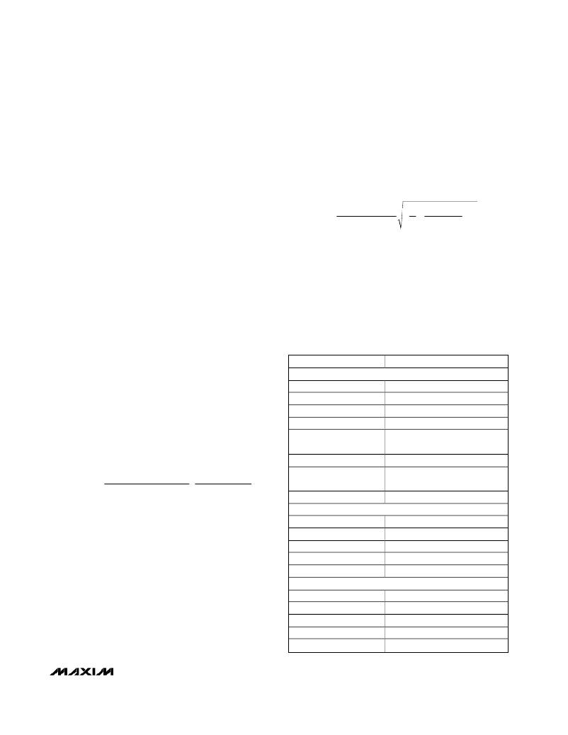
�Table� 2.� Component� Suppliers�
�load� current� with� acceptable� voltage� ripple.� The� output�
�ripple� has� two� components:� variations� in� the� charge�
�stored� in� the� output� capacitor� with� each� LX� pulse,� and�
�the� voltage� drop� across� the� capacitor� ’� s� equivalent�
�series� resistance� (ESR)� caused� by� the� current� into� and�
�out� of� the� capacitor:�
�V� RIPPLE� ?� V� RIPPLE(ESR)� +� V� RIPPLE(C)�
�The� output� voltage� ripple� as� a� consequence� of� the� ESR�
�and� output� capacitance� is:�
�V� RIPPLE(ESR)� =� ESR� � I� PEAK�
�SUPPLIER�
�DIODES�
�Central� Semiconductor�
�Fairchild�
�General� Semiconductor�
�International� Rectifier�
�Nihon�
�On� Semi�
�WEBSITE�
�www.centralsemi.com�
�www.fairchildsemi.com�
�www.gensemi.com�
�www.irf.com�
�www.niec.co.jp/engver2/�
�niec.co.jp_eg.htm�
�www.onsemi.com�
�L� � (� I� PEAK� -� I� OUTPUT� )� ?�
�?�
�V� RIPPLE(C)� =�
�2�
�V� IN�
�?� ?�
�2� C� OUT� � V� OUTPUT� ?� V� IN� -� V� OUTPUT� ?�
�Vishay-Siliconix�
�Zetex�
�www.vishay.com/brands/siliconix/�
�main.html�
�www.zetex.com�
�where� I� PEAK� is� the� peak� inductor� current� (see� Inductor�
�CAPACITORS�
�Selection� ).� The� worst-case� ripple� occurs� at� no-load.�
�These� equations� are� suitable� for� initial� capacitor� selec-�
�tion,� but� final� values� should� be� set� by� testing� a� proto-�
�type� or� evaluation� circuit.� As� a� general� rule,� a� smaller�
�amount� of� charge� delivered� in� each� pulse� results� in�
�less� output� ripple.� Since� the� amount� of� charge� deliv-�
�ered� in� each� oscillator� pulse� is� determined� by� the�
�inductor� value� and� input� voltage,� the� voltage� ripple�
�increases� with� larger� inductance,� and� as� the� input� volt-�
�age� decreases.� See� Table� 3� for� recommended� capaci-�
�tor� values� and� Table� 2� for� recommended� component�
�manufacturers.�
�AVX�
�Kemet�
�Nichicon�
�Sanyo�
�Taiyo� Yuden�
�INDUCTORS�
�Coilcraft�
�Coiltronics�
�Pulse� Engineering�
�Sumida� USA�
�Toko�
�www.avxcorp.com�
�www.kemet.com�
�www.nichicon-us.com�
�www.sanyo.com�
�www.t-yuden.com�
�www.coilcraft.com�
�www.cooperet.com�
�www.pulseeng.com�
�www.sumida.com�
�www.tokoam.com�
�______________________________________________________________________________________�
�11�
�相关PDF资料 |
PDF描述 |
|---|---|
| RBM40DRMI-S288 | CONN EDGECARD 80POS .156 EXTEND |
| MAX6792TPZD0+T | IC REG LIN W/SPR VSR 20-TQFN |
| MAX6792TPZD2+T | IC REG LIN W/SPR VSR 20-TQFN |
| MAX755ESA+T | IC REG INV ADJ 0.2A 8SOIC |
| MAX6792TPZD1+T | IC REG LIN W/SPR VSR 20-TQFN |
相关代理商/技术参数 |
参数描述 |
|---|---|
| MAX1776EVKIT | 功能描述:直流/直流开关转换器 Evaluation Kit for the MAX1776 RoHS:否 制造商:STMicroelectronics 最大输入电压:4.5 V 开关频率:1.5 MHz 输出电压:4.6 V 输出电流:250 mA 输出端数量:2 最大工作温度:+ 85 C 安装风格:SMD/SMT |
| MAX1777EEI | 功能描述:DC/DC 开关控制器 RoHS:否 制造商:Texas Instruments 输入电压:6 V to 100 V 开关频率: 输出电压:1.215 V to 80 V 输出电流:3.5 A 输出端数量:1 最大工作温度:+ 125 C 安装风格: 封装 / 箱体:CPAK |
| MAX1777EEI+ | 功能描述:DC/DC 开关控制器 Quad-Out Main Power Sply Ctlr for Ntbk RoHS:否 制造商:Texas Instruments 输入电压:6 V to 100 V 开关频率: 输出电压:1.215 V to 80 V 输出电流:3.5 A 输出端数量:1 最大工作温度:+ 125 C 安装风格: 封装 / 箱体:CPAK |
| MAX1777EEI+T | 功能描述:DC/DC 开关控制器 Quad-Out Main Power Sply Ctlr for Ntbk RoHS:否 制造商:Texas Instruments 输入电压:6 V to 100 V 开关频率: 输出电压:1.215 V to 80 V 输出电流:3.5 A 输出端数量:1 最大工作温度:+ 125 C 安装风格: 封装 / 箱体:CPAK |
| MAX1777EEI-T | 功能描述:DC/DC 开关控制器 RoHS:否 制造商:Texas Instruments 输入电压:6 V to 100 V 开关频率: 输出电压:1.215 V to 80 V 输出电流:3.5 A 输出端数量:1 最大工作温度:+ 125 C 安装风格: 封装 / 箱体:CPAK |
发布紧急采购,3分钟左右您将得到回复。