- 您现在的位置:买卖IC网 > PDF目录19343 > MAX1805MEE+T (Maxim Integrated)IC TEMP SENSOR REMOTE 16-QSOP PDF资料下载
参数资料
| 型号: | MAX1805MEE+T |
| 厂商: | Maxim Integrated |
| 文件页数: | 9/17页 |
| 文件大小: | 497K |
| 描述: | IC TEMP SENSOR REMOTE 16-QSOP |
| 产品培训模块: | Lead (SnPb) Finish for COTS Obsolescence Mitigation Program |
| 标准包装: | 2,500 |
| 功能: | 温度计,恒温计 |
| 传感器类型: | 内部和外部 |
| 感应温度: | -55°C ~ 125°C,外部传感器 |
| 精确度: | ±3.5°C 本地(最大),±5°C 远程(最大) |
| 拓扑: | ADC,比较器,多路复用器,寄存器库 |
| 输出类型: | I²C?/SMBus? |
| 输出警报: | 是 |
| 输出风扇: | 无 |
| 电源电压: | 3 V ~ 5.5 V |
| 工作温度: | -55°C ~ 125°C |
| 安装类型: | 表面贴装 |
| 封装/外壳: | 16-SSOP(0.154",3.90mm 宽) |
| 供应商设备封装: | 16-QSOP |
| 包装: | 带卷 (TR) |
be 4in to 8in (typ) or more as long as the worst noise
sources (such as CRTs, clock generators, memory
buses, and ISA/PCI buses) are avoided.
2) Do not route the DXP_ to DXN_ lines next to the
deflection coils of a CRT. Also, do not route the
traces across a fast memory bus, which can easily
introduce +30癈 error, even with good filtering.
Otherwise, most noise sources are fairly benign.
3) Route the DXP_ and DXN_ traces in parallel and in
close proximity to each other, away from any high-
voltage traces such as +12VDC. Leakage currents
from PC board contamination must be dealt with
carefully, since a 20M& leakage path from DXP_ to
ground causes about +1癈 error.
4) Connect guard traces to GND on either side of the
DXP_ to DXN_ traces (Figure 2). With guard traces
in place, routing near high-voltage traces is no
longer an issue.
5) Route through as few vias and crossunders as possi-
ble to minimize copper/solder thermocouple effects.
6) When introducing a thermocouple, make sure that
both the DXP_ and the DXN_ paths have matching
thermocouples. In general, PC board-induced ther-
mocouples are not a serious problem. A copper-sol-
der thermocouple exhibits 3礦/癈, and it takes
about 200礦 of voltage error at DXP_ to DXN_ to
cause a +1癈 measurement error. So, most para-
sitic thermocouple errors are swamped out.
7) Use wide traces. Narrow ones are more inductive
and tend to pick up radiated noise. The 10mil
widths and spacings recommended in Figure 2 are
not absolutely necessary (as they offer only a minor
improvement in leakage and noise), but try to use
them where practical.
8) Copper cannot be used as an EMI shield, and only
ferrous materials such as steel work well. Placing a
copper ground plane between the DXP_ to DXN_
traces and traces carrying high-frequency noise sig-
nals does not help reduce EMI.
PC Board Layout Checklist
" Place the MAX1668/MAX1805/MAX1989 as close as
possible to the remote diodes.
" Keep traces away from high voltages (+12V bus).
" Keep traces away from fast data buses and CRTs.
" Use recommended trace widths and spacings.
" Place a ground plane under the traces.
" Use guard traces flanking DXP_ and DXN_ and con-
necting to GND.
" Place the noise filter and the 0.1礔 V
CC
bypass
capacitors close to the MAX1668/MAX1805/
MAX1989.
" Add a 200& resistor in series with V
CC
for best noise
filtering (see the Typical Operating Circuit).
Twisted-Pair and Shielded Cables
For remote-sensor distances longer than 8in, or in partic-
ularly noisy environments, a twisted pair is recommend-
ed. Its practical length is 6ft to 12ft (typ) before noise
becomes a problem, as tested in a noisy electronics lab-
oratory. For longer distances, the best solution is a
shielded twisted pair like that used for audio micro-
phones. For example, Belden #8451 works well for dis-
tances up to 100ft in a noisy environment. Connect the
twisted pair to DXP_ and DXN_ and the shield to GND,
and leave the shields remote end unterminated.
Excess capacitance at DX_ _ limits practical remote-sen-
sor distances (see the Typical Operating Characteristics).
For very long cable runs, the cables parasitic capaci-
tance often provides noise filtering, so the 2200pF capac-
itor can often be removed or reduced in value.
Cable resistance also affects remote-sensor accuracy;
1& series resistance introduces about +0.5癈 error.
Low-Power Standby Mode
Standby mode disables the ADC and reduces the sup-
ply-current drain to less than 12礎. Enter standby
mode by forcing the STBY pin low or through the
RUN/STOP bit in the configuration byte register.
Hardware and software standby modes behave almost
identically: all data is retained in memory, and the SMB
interface is alive and listening for reads and writes.
Activate hardware standby mode by forcing the STBY
pin low. In a notebook computer, this line can be con-
nected to the system SUSTAT# suspend-state signal.
The STBY pin low state overrides any software conversion
command. If a hardware or software standby command
is received while a conversion is in progress, the conver-
Multichannel Remote/Local
Temperature Sensors
_______________________________________________________________________________________ 9
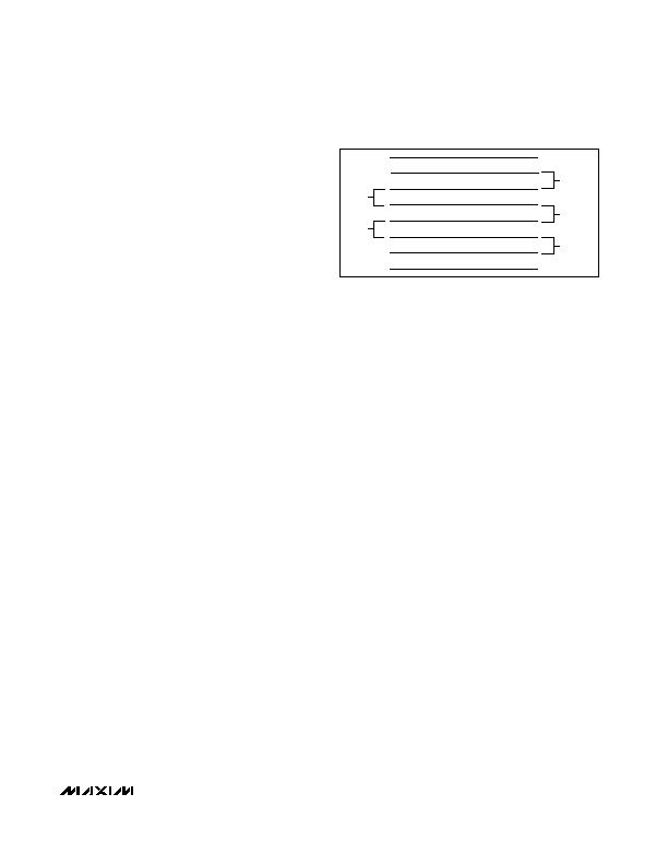
MINIMUM
10mils
10mils
10mils
10mils
GND
GND
DXN_
DXP_
Figure 2. Recommended DXP_/DXN_ PC Traces
相关PDF资料 |
PDF描述 |
|---|---|
| TMS320C6414TZLZ7 | IC DSP FIXED-POINT 532-FCBGA |
| JWS60024 | PWR SUP 24.0V 27A SNG OUTPUT |
| AMC18DRYN-S734 | CONN EDGECARD 36POS DIP .100 SLD |
| A54SX16A-TQG100 | IC FPGA 180I/O 100TQFP |
| A40MX04-VQG80 | IC FPGA 69I/O 80VQFP |
相关代理商/技术参数 |
参数描述 |
|---|---|
| MAX1806EUA08 | 功能描述:低压差稳压器 - LDO 500mA RoHS:否 制造商:Texas Instruments 最大输入电压:36 V 输出电压:1.4 V to 20.5 V 回动电压(最大值):307 mV 输出电流:1 A 负载调节:0.3 % 输出端数量: 输出类型:Fixed 最大工作温度:+ 125 C 安装风格:SMD/SMT 封装 / 箱体:VQFN-20 |
| MAX1806EUA08+ | 功能描述:低压差稳压器 - LDO 500mA RoHS:否 制造商:Texas Instruments 最大输入电压:36 V 输出电压:1.4 V to 20.5 V 回动电压(最大值):307 mV 输出电流:1 A 负载调节:0.3 % 输出端数量: 输出类型:Fixed 最大工作温度:+ 125 C 安装风格:SMD/SMT 封装 / 箱体:VQFN-20 |
| MAX1806EUA08+T | 功能描述:低压差稳压器 - LDO 500mA RoHS:否 制造商:Texas Instruments 最大输入电压:36 V 输出电压:1.4 V to 20.5 V 回动电压(最大值):307 mV 输出电流:1 A 负载调节:0.3 % 输出端数量: 输出类型:Fixed 最大工作温度:+ 125 C 安装风格:SMD/SMT 封装 / 箱体:VQFN-20 |
| MAX1806EUA08+TG48 | 制造商:Maxim Integrated Products 功能描述:- Tape and Reel |
| MAX1806EUA08-T | 功能描述:低压差稳压器 - LDO 500mA RoHS:否 制造商:Texas Instruments 最大输入电压:36 V 输出电压:1.4 V to 20.5 V 回动电压(最大值):307 mV 输出电流:1 A 负载调节:0.3 % 输出端数量: 输出类型:Fixed 最大工作温度:+ 125 C 安装风格:SMD/SMT 封装 / 箱体:VQFN-20 |
发布紧急采购,3分钟左右您将得到回复。