- 您现在的位置:买卖IC网 > PDF目录15147 > MAX1846EUB+T (Maxim Integrated Products)IC REG CTRLR FLYBK INV CM 10UMAX PDF资料下载
参数资料
| 型号: | MAX1846EUB+T |
| 厂商: | Maxim Integrated Products |
| 文件页数: | 12/20页 |
| 文件大小: | 0K |
| 描述: | IC REG CTRLR FLYBK INV CM 10UMAX |
| 产品培训模块: | Lead (SnPb) Finish for COTS Obsolescence Mitigation Program |
| 标准包装: | 2,500 |
| PWM 型: | 电流模式 |
| 输出数: | 1 |
| 频率 - 最大: | 345kHz |
| 占空比: | 98% |
| 电源电压: | 3 V ~ 16.5 V |
| 降压: | 无 |
| 升压: | 无 |
| 回扫: | 是 |
| 反相: | 是 |
| 倍增器: | 无 |
| 除法器: | 无 |
| Cuk: | 无 |
| 隔离: | 无 |
| 工作温度: | -40°C ~ 85°C |
| 封装/外壳: | 10-TFSOP,10-MSOP(0.118",3.00mm 宽) |
| 包装: | 带卷 (TR) |
�� �
�
�High-Efficiency,� Current-Mode,�
�Inverting� PWM� Controller�
�V� IN�
�+12V�
�12.2� μ� H�
�12� μ� F� VP1-0190�
�25V�
�1:4�
�0.47� μ� F�
�8�
�16�
�2� 1�
�VL� POL�
�SHDN�
�SYNC�
�15�
�IN�
�EXT�
�CS�
�14�
�13�
�IRLL2705�
�CMR1U-02�
�470� ?�
�100pF�
�100V�
�V� OUT�
�-48V� AT� 100mA�
�12� μ� F�
�100V�
�0.033� μ� F�
�270k� ?�
�4�
�3�
�MAX1847�
�COMP�
�FREQ�
�N.C.�
�PGND�
�7,� 9�
�12�
�0.05� ?�
�0.5W�
�383k� ?�
�1%�
�150k� ?�
�5�
�REF�
�FB�
�GND�
�10,� 11�
�6�
�1800pF�
�10.0k� ?�
�1%�
�0.1� μ� F�
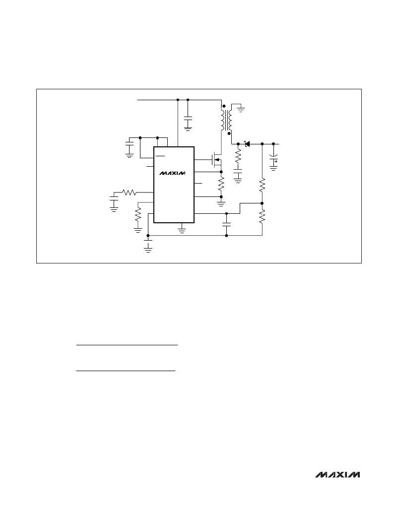
�Figure� 1.� Using� an� N-Channel� MOSFET� (MAX1847� only)�
�Calculate� the� Duty� Cycle�
�The� duty� cycle� is� the� ratio� of� the� on-time� of� the� MOSFET�
�switch� to� the� oscillator� period.� It� is� determined� by� the�
�ratio� of� the� input� voltage� to� the� output� voltage.� Since�
�the� input� voltage� typically� has� a� range� of� operation,� a�
�minimum� (D� MIN� )� and� maximum� (D� MAX� )� duty� cycle� is�
�calculated� by:�
�1.25V� and� the� regulation� voltage� for� FB� is� nominally� 0.�
�The� load� presented� to� the� reference� by� the� feedback�
�resistors� must� be� less� than� 500μA� to� guarantee� that�
�V� REF� is� in� regulation� (see� Electrical� Characteristics�
�Table).� Conversely,� the� current� through� the� feedback�
�resistors� must� be� large� enough� so� that� the� leakage� cur-�
�rent� of� the� FB� input� (50nA)� is� insignificant.� Therefore,�
�D� MIN� =�
�D� MAX� =�
�?� V� OUT� +� V� D�
�V� IN� (� MAX� )� ?� V� SW� ?� V� LIM� ?� V� OUT� +� V� D�
�?� V� OUT� +� V� D�
�V� IN� (� MIN� )� ?� V� SW� ?� V� LIM� ?� V� OUT� +� V� D�
�select� R2� so� that� I� R2� is� between� 50μA� and� 250μA.�
�I� R2� =� V� REF� /� R2�
�where� V� REF� =� 1.25V.� A� typical� value� for� R2� is� 10k� ?� .�
�Once� R2� is� selected,� calculate� R1� with� the� following�
�equation:�
�R1� =� R2� x� (-V� OUT� /� V� REF� )�
�where� V� D� is� the� forward� drop� across� the� output� diode,�
�V� SW� is� the� drop� across� the� external� FET� when� on,� and�
�V� LIM� is� the� current-limit� threshold.� To� begin� with,�
�assume� V� D� =� 0.5V� for� a� Schottky� diode,� V� SW� =� 100mV,�
�and� V� LIM� =� 100mV.� Remember� that� V� OUT� is� negative�
�when� using� this� formula.�
�Setting� the� Output� Voltage�
�The� output� voltage� is� set� using� two� external� resistors� to�
�form� a� resistive-divider� to� FB� between� the� output� and�
�REF� (refer� to� R1� and� R2� in� Figure� 1).� V� REF� is� nominally�
�Setting� the� Operating� Frequency�
�The� MAX1846/MAX1847� are� capable� of� operating� at�
�switching� frequencies� from� 100kHz� to� 500kHz.� Choice�
�of� operating� frequency� depends� on� a� number� of� fac-�
�tors:�
�1)� Noise� considerations� may� dictate� setting� (or� syn-�
�chronizing)� f� OSC� above� or� below� a� certain� fre-�
�quency� or� band� of� frequencies,� particularly� in� RF�
�applications.�
�12�
�______________________________________________________________________________________�
�相关PDF资料 |
PDF描述 |
|---|---|
| MAX773CSD+ | IC REG CTRLR BST PWM 8-SOIC |
| MAX772CSA+ | IC REG CTRLR BST PWM 8-SOIC |
| ISL88013IH531Z-TK | IC VOLTAGE MONITOR DUAL SOT23-5 |
| MAX608ESA+T | IC REG CTRLR BST PWM 8-SOIC |
| MAX608EPA+ | IC REG CTRLR BST PWM 8-PDIP |
相关代理商/技术参数 |
参数描述 |
|---|---|
| MAX1846EVKIT | 功能描述:电流型 PWM 控制器 Evaluation Kit for the MAX1846 MAX1847 RoHS:否 制造商:Texas Instruments 开关频率:27 KHz 上升时间: 下降时间: 工作电源电压:6 V to 15 V 工作电源电流:1.5 mA 输出端数量:1 最大工作温度:+ 105 C 安装风格:SMD/SMT 封装 / 箱体:TSSOP-14 |
| MAX1847EEE | 功能描述:电流型 PWM 控制器 RoHS:否 制造商:Texas Instruments 开关频率:27 KHz 上升时间: 下降时间: 工作电源电压:6 V to 15 V 工作电源电流:1.5 mA 输出端数量:1 最大工作温度:+ 105 C 安装风格:SMD/SMT 封装 / 箱体:TSSOP-14 |
| MAX1847EEE+ | 功能描述:电流型 PWM 控制器 Current-Mode Invert PWM Controller RoHS:否 制造商:Texas Instruments 开关频率:27 KHz 上升时间: 下降时间: 工作电源电压:6 V to 15 V 工作电源电流:1.5 mA 输出端数量:1 最大工作温度:+ 105 C 安装风格:SMD/SMT 封装 / 箱体:TSSOP-14 |
| MAX1847EEE+ | 制造商:Maxim Integrated Products 功能描述:PWM CONTROLLER ((NW)) |
| MAX1847EEE+T | 功能描述:电流型 PWM 控制器 Current-Mode Invert PWM Controller RoHS:否 制造商:Texas Instruments 开关频率:27 KHz 上升时间: 下降时间: 工作电源电压:6 V to 15 V 工作电源电流:1.5 mA 输出端数量:1 最大工作温度:+ 105 C 安装风格:SMD/SMT 封装 / 箱体:TSSOP-14 |
发布紧急采购,3分钟左右您将得到回复。