- 您现在的位置:买卖IC网 > PDF目录15488 > MAX1858AEEG+ (Maxim Integrated Products)IC REG CTRLR BUCK PWM VM 24-QSOP PDF资料下载
参数资料
| 型号: | MAX1858AEEG+ |
| 厂商: | Maxim Integrated Products |
| 文件页数: | 6/22页 |
| 文件大小: | 0K |
| 描述: | IC REG CTRLR BUCK PWM VM 24-QSOP |
| 产品培训模块: | Lead (SnPb) Finish for COTS Obsolescence Mitigation Program |
| 标准包装: | 50 |
| PWM 型: | 电压模式 |
| 输出数: | 2 |
| 频率 - 最大: | 660kHz |
| 电源电压: | 4.5 V ~ 23 V |
| 降压: | 是 |
| 升压: | 无 |
| 回扫: | 无 |
| 反相: | 无 |
| 倍增器: | 无 |
| 除法器: | 无 |
| Cuk: | 无 |
| 隔离: | 无 |
| 工作温度: | -40°C ~ 85°C |
| 封装/外壳: | 24-SSOP(0.154",3.90mm 宽) |
| 包装: | 管件 |
�� �
�
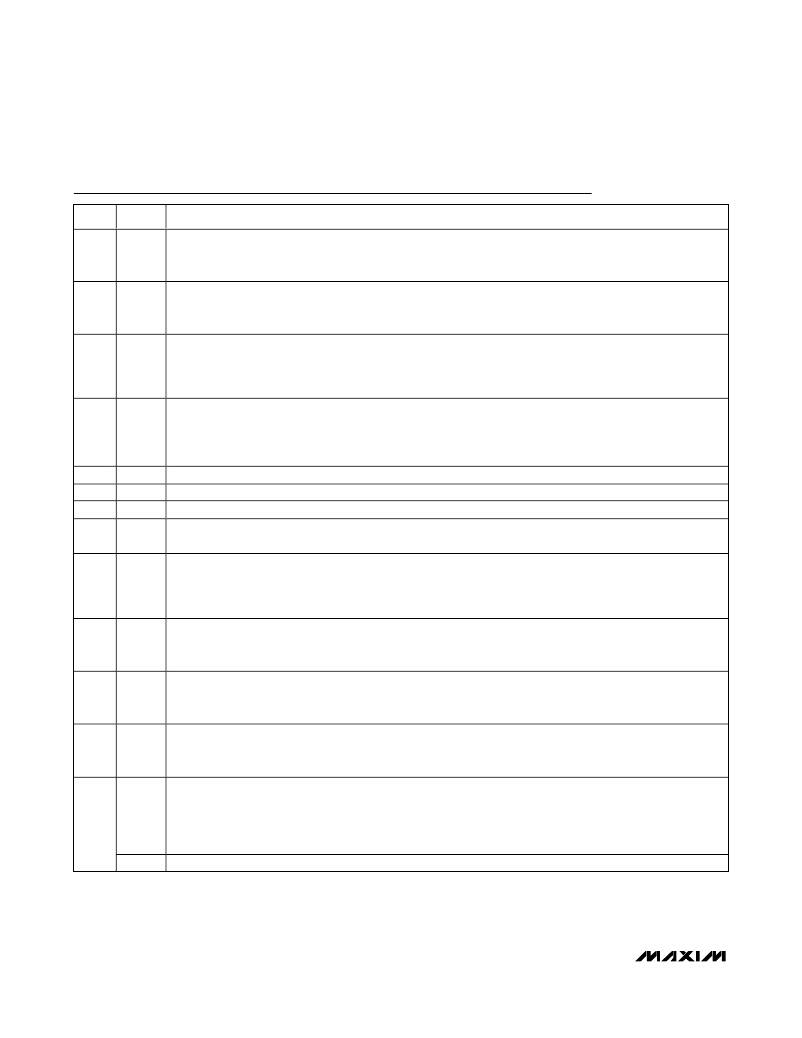
�Dual� 180°� Out-of-Phase� Buck� Controllers� with�
�Sequencing/Prebias� Startup� and� POR�
�Pin� Description�
�PIN�
�NAME�
�FUNCTION�
�Compensation� Pin� for� Regulator� 2� (REG2).� Compensate� REG2’s� control� loop� by� connecting� a� series� resistor�
�1�
�COMP2� (R� COMP2� )� and� capacitor� (C� COMP2A� )� to� GND� in� parallel� with� a� second� compensation� capacitor� (C� COMP2B� )� as�
�shown� in� Figure� 1.�
�Feedback� Input� for� Regulator� 2� (REG2).� Connect� FB2� to� a� resistive� divider� between� REG2’s� output� and� GND� to�
�2�
�3�
�4�
�5�
�6�
�7�
�8�
�9�
�10�
�11�
�FB2�
�ILIM2�
�OSC�
�V+�
�REF�
�GND�
�CKO�
�SYNC�
�ILIM1�
�FB1�
�adjust� the� output� voltage� between� 1V� and� 18V.� To� set� the� output� voltage� below� 1V,� connect� FB2� to� a� resistive�
�voltage-divider� from� REF� to� REG2’s� output.� See� the� Setting� the� Output� Voltage� section.�
�Current-Limit� Adjustment� for� Regulator� 2� (REG2).� The� PGND–LX2� current-limit� threshold� defaults� to� 100mV� if�
�ILIM2� is� connected� to� V� L� .� Connect� a� resistor� (R� ILIM2� )� from� ILIM2� to� GND� to� adjust� the� REG2’s� current-limit�
�threshold� (V� ITH2� )� from� 50mV� (R� ILIM2� =� 100k� ?� )� to� 300mV� (R� ILIM2� =� 600k� ?� ).� See� the� Setting� the� Valley� Current�
�Limit� section.�
�Oscillator� Frequency� Set� Input.� Connect� a� resistor� from� OSC� to� GND� (R� OSC� )� to� set� the� switching� frequency� from�
�100kHz� (R� OSC� =� 60k� ?� )� to� 600kHz� (R� OSC� =� 10k� ?� ).� The� controller� still� requires� R� OSC� when� an� external� clock� is�
�connected� to� SYNC.� When� using� an� external� clock,� select� R� OSC� as� described� above,� and� set� the� external� clock�
�frequency� to� twice� the� desired� switching� frequency.�
�Input� Supply� Voltage.� 4.5V� to� 23V.�
�2V� Reference� Output.� Bypass� to� GND� with� a� 0.22μF� or� greater� ceramic� capacitor.�
�Analog� Ground�
�Clock� Output.� Clock� output� for� external� 2-� or� 4-phase� synchronization� (see� the� Clock� Synchronization� (SYNC,�
�CKO)� section).�
�Synchronization� Input� or� Clock� Output� Selection� Input.� SYNC� has� three� operating� modes.� Connect� SYNC� to� a�
�200kHz� to� 1200kHz� clock� for� external� synchronization.� Connect� SYNC� to� GND� for� 2-phase� operation� as� a� master�
�controller.� Connect� SYNC� to� V� L� for� 4-phase� operation� as� a� master� controller� (see� the� Clock� Synchronization�
�(SYNC,� CKO)� section).�
�Current-Limit� Adjustment� for� Regulator� 1� (REG1).� The� PGND–LX1� current-limit� threshold� defaults� to� 100mV� if�
�ILIM1� is� connected� to� V� L� .� Connect� a� resistor� (R� ILIM1� )� from� ILIM1� to� GND� to� adjust� REG1’s� current-limit� threshold�
�(V� ITH1� )� from� 50mV� (R� ILIM1� =� 100k� ?� )� to� 300mV� (R� ILIM1� =� 600k� ?� ).� See� the� Setting� the� Valley� Current� Limit� section.�
�Feedback� Input� for� Regulator� 1� (REG1).� Connect� FB1� to� a� resistive� divider� between� REG1’s� output� and� GND� to�
�adjust� the� output� voltage� between� 1V� and� 18V.� To� set� the� output� voltage� below� 1V,� connect� FB1� to� a� resistive�
�voltage-divider� from� REF� and� REG1’s� output.� See� the� Setting� the� Output� Voltage� section.�
�Compensation� Pin� for� Regulator� 1� (REG1).� Compensate� REG1’s� control� loop� by� connecting� a� series� resistor�
�12�
�COMP1� (R� COMP1� )� and� capacitor� (C� COMP1A� )� to� GND� in� parallel� with� a� second� compensation� capacitor� (C� COMP1B� )� as�
�shown� in� Figure� 1.�
�Open-Drain� Reset� Output� (MAX1858A/MAX1876A� Only).� RST� is� low� when� either� output� voltage� is� more� than� 10%�
�below� its� regulation� point.� After� soft-start� is� completed� and� both� outputs� exceed� 90%� of� their� nominal� output�
�13�
�RST�
�N.C.�
�voltage� (V� FB� _� >� 0.9V),� RST� becomes� high� impedance� after� a� 140ms� delay� and� remains� high� impedance� as� long�
�as� both� outputs� maintain� regulation.� Connect� a� resistor� between� RST� and� the� logic� supply� for� logic-level�
�voltages.�
�Connect� to� GND� or� leave� unconnected� for� the� MAX1875A.�
�6�
�_______________________________________________________________________________________�
�相关PDF资料 |
PDF描述 |
|---|---|
| GBC30DRYH-S93 | CONN EDGECARD 60POS DIP .100 SLD |
| GBC31DRTS-S93 | CONN EDGECARD 62POS DIP .100 SLD |
| MAX1876AEEG+ | IC REG CTRLR BUCK PWM VM 24-QSOP |
| GCC20DRTN-S93 | CONN EDGECARD 40POS DIP .100 SLD |
| MAX1771EPA+ | IC REG CTRLR BST PWM 8-DIP |
相关代理商/技术参数 |
参数描述 |
|---|---|
| MAX1858AEEG+ | 功能描述:电压模式 PWM 控制器 Dual 180 Out Buck Controllers RoHS:否 制造商:Texas Instruments 输出端数量:1 拓扑结构:Buck 输出电压:34 V 输出电流: 开关频率: 工作电源电压:4.5 V to 5.5 V 电源电流:600 uA 最大工作温度:+ 125 C 最小工作温度:- 40 C 封装 / 箱体:WSON-8 封装:Reel |
| MAX1858AEEG+T | 功能描述:电压模式 PWM 控制器 Dual 180 Out Buck Controllers RoHS:否 制造商:Texas Instruments 输出端数量:1 拓扑结构:Buck 输出电压:34 V 输出电流: 开关频率: 工作电源电压:4.5 V to 5.5 V 电源电流:600 uA 最大工作温度:+ 125 C 最小工作温度:- 40 C 封装 / 箱体:WSON-8 封装:Reel |
| MAX1858AEEG-T | 功能描述:DC/DC 开关控制器 RoHS:否 制造商:Texas Instruments 输入电压:6 V to 100 V 开关频率: 输出电压:1.215 V to 80 V 输出电流:3.5 A 输出端数量:1 最大工作温度:+ 125 C 安装风格: 封装 / 箱体:CPAK |
| MAX1858EEG | 功能描述:DC/DC 开关控制器 RoHS:否 制造商:Texas Instruments 输入电压:6 V to 100 V 开关频率: 输出电压:1.215 V to 80 V 输出电流:3.5 A 输出端数量:1 最大工作温度:+ 125 C 安装风格: 封装 / 箱体:CPAK |
| MAX1858EEG+ | 功能描述:电压模式 PWM 控制器 Dual 180 Out Buck Controllers RoHS:否 制造商:Texas Instruments 输出端数量:1 拓扑结构:Buck 输出电压:34 V 输出电流: 开关频率: 工作电源电压:4.5 V to 5.5 V 电源电流:600 uA 最大工作温度:+ 125 C 最小工作温度:- 40 C 封装 / 箱体:WSON-8 封装:Reel |
发布紧急采购,3分钟左右您将得到回复。