- 您现在的位置:买卖IC网 > PDF目录383341 > MAX1921EUT-T (Maxim Integrated Products, Inc.) Low-Voltage, 400mA Step-Down DC-DC Converters in SOT23 PDF资料下载
参数资料
| 型号: | MAX1921EUT-T |
| 厂商: | Maxim Integrated Products, Inc. |
| 元件分类: | DC/DC变换器 |
| 英文描述: | Low-Voltage, 400mA Step-Down DC-DC Converters in SOT23 |
| 中文描述: | 低电压,400mA的降压型DC - DC转换器采用SOT23 |
| 文件页数: | 6/9页 |
| 文件大小: | 370K |
| 代理商: | MAX1921EUT-T |
M
Design Procedure
The MAX1920/MAX1921 are optimized for small external
components and fast transient response. There are
several application circuits (Figures 1 through 4) to
allow the choice between ceramic or tantalum output
capacitor and internally or externally set output volt-
ages. The use of a small ceramic output capacitor is
preferred for higher reliability, improved voltage-posi-
tioning transient response, reduced output ripple, and
the smaller size and greater availability of ceramic versus
tantalum capacitors.
Voltage Positioning
Figures 1 and 2 are the application circuits that utilize
small ceramic output capacitors. For stability, the circuit
obtains feedback from the LX node through R1, while
load transients are fed-forward through C
FF
. Because
there is no D.C. feedback from the output, the output volt-
age exhibits load regulation that is equal to the output
load current multiplied by the inductor
’
s series resistance.
This small amount of load regulation is similar to voltage
positioning as used by high-powered microprocessor
supplies intended for personal computers. For the
MAX1920/MAX1921, voltage positioning eliminates or
greatly reduces undershoot and overshoot during load
transients (see the
Typical Operating Characteristics
),
which effectively halves the peak-to-peak output voltage
excursions compared to traditional step-down converters.
For convenience, Table 1 lists the recommended external
component values for use with the MAX1921 application
circuit of Figure 1 with various input and output voltages.
Inductor Selection
In order to calculate the smallest inductor, several cal-
culations are needed. First, calculate the maximum
duty cycle of the application as:
Second, calculate the critical voltage across the inductor as:
if DutyCycle(MAX) < 50%,
then V
CRITICAL
= (V
IN
(MIN) - V
OUT
),
else V
CRITICAL
= V
OUT
Last, calculate the minimum inductor value as:
Select the next standard value larger than L(MIN). The
L(MIN) calculation already includes a margin for induc-
tance tolerance. Although values much larger than
L(MIN) work, transient performance, efficiency, and
inductor size suffer.
A 550mA rated inductor is enough to prevent saturation
for output currents up to 400mA. Saturation occurs
when the inductor
’
s magnetic flux density reaches the
maximum level the core can support and inductance
falls. Choose a low DC-resistance inductor to improve
efficiency. Tables 2 and 3 list some suggested inductors
and suppliers.
L MIN
(
V
CRITICAL
)
.
=
×
2 5 10
6
DutyCycle MAX
V
V
MIN
(
OUT
IN
(
)
)
%
=
×
100
Low-Voltage, 400mA Step-Down
DC-DC Converters in SOT23
6
_______________________________________________________________________________________
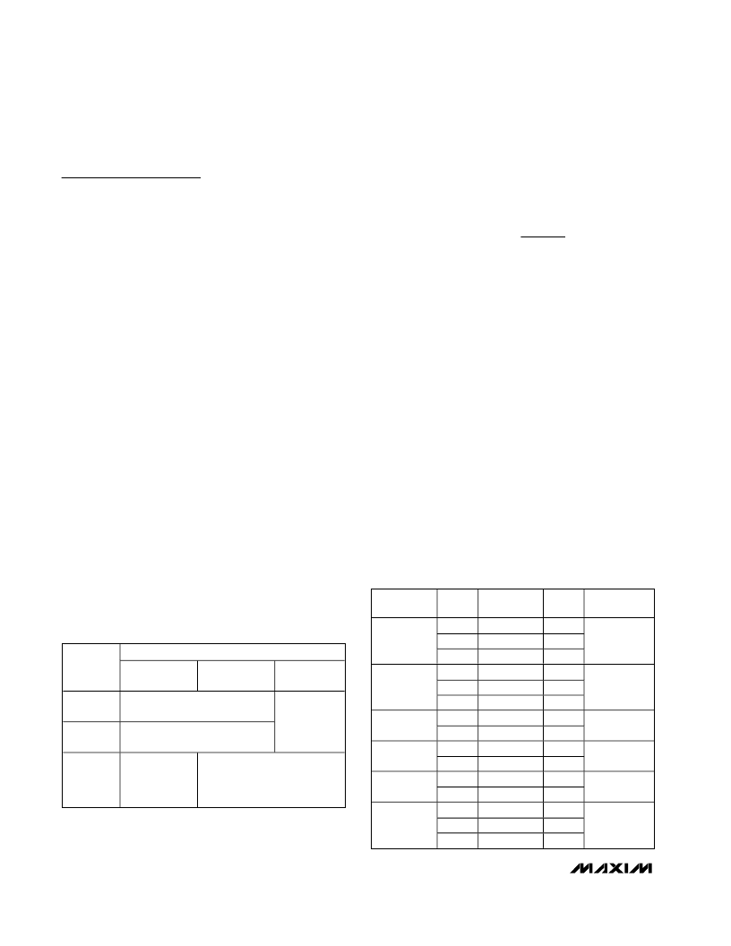
Table 1. MAX1921 Suggested
Components for Figure 1
INPUT SOURCE
OUTPUT
5V
3.3V, 1 Li+,
3 x AA
2.5V, 2 x AA
3.3V
3.0V
L = 10μH, C
OUT
= 10μF,
R1 = 8.25k
, C
FF
= 3300pF
2.5V
L = 6.8μH, C
OUT
= 6.8μF,
R1 = 5.62k
, C
FF
= 4700pF
N/A
1.8V
1.5V
L = 10μH,
C
OUT
= 10μF,
R1 = 8.25k
,
C
FF
= 3300pF
L = 4.7μH, C
OUT
= 4.7μF,
R1 = 4.75k
, C
FF
= 5600pF
Table 2. Suggested Inductors
PART
NUMBER
L
(μH)
R
L
(ohms max)
Isat (A)
SIZE
4.7
6.8
10
4.7
6.8
10
4.7
6.8
4.7
10
4.7
10
4.7
6.8
10
0.200
0.320
0.410
0.080
0.095
0.160
0.081
0.108
0.38
0.79
0.230
0.490
0.087
0.105
0.150
1.10
0.90
0.80
0.90
0.73
0.55
0.63
0.57
0.74
0.50
0.84
0.55
1.14
0.95
0.76
Coilcraft
LPO1704
6.6 x 5.5 x 1.0
= 36.3mm
3
Sumida
CDRH3D16
3.8 x 3.8 x 1.8
= 26.0mm
3
Sumida
CDRH2D18
3.2 x 3.2 x 2.0
= 20.5mm
3
Toko
D312F
3.6 x 3.6 x 1.2
= 15.6mm
3
Toko
D412F
4.6 x 4.6 x 1.2
= 25.4mm
3
Toko
D52LC
5.0 x 5.0 x 2.0
= 50.0mm
3
相关PDF资料 |
PDF描述 |
|---|---|
| MAX1922 | 1A Current-Limited Switch for 2 USB Ports |
| MAX1922ESA | 1A Current-Limited Switch for 2 USB Ports |
| MAX1924X | Li+ Battery-Pack Protector with Integrated Fuse Driver |
| MAX1906XEGE | Li+ Battery-Pack Protector with Integrated Fuse Driver |
| MAX1906 | Li+ Battery-Pack Protector with Integrated Fuse Driver |
相关代理商/技术参数 |
参数描述 |
|---|---|
| MAX1921EVKIT | 功能描述:电源管理IC开发工具 MAX1921 Eval Kit RoHS:否 制造商:Maxim Integrated 产品:Evaluation Kits 类型:Battery Management 工具用于评估:MAX17710GB 输入电压: 输出电压:1.8 V |
| MAX1922ESA | 功能描述:电源开关 IC - USB 1A Crnt-Ltd Switch for 2 USB Ports RoHS:否 制造商:Micrel 电源电压-最小:2.7 V 电源电压-最大:5.5 V 最大工作温度:+ 85 C 最小工作温度:- 40 C 封装 / 箱体:SOIC-8 封装:Tube |
| MAX1922ESA+ | 功能描述:电源开关 IC - USB 1A Crnt-Ltd Switch for 2 USB Ports RoHS:否 制造商:Micrel 电源电压-最小:2.7 V 电源电压-最大:5.5 V 最大工作温度:+ 85 C 最小工作温度:- 40 C 封装 / 箱体:SOIC-8 封装:Tube |
| MAX1922ESA+C71073 | 功能描述:电源开关 IC - USB 1A Crnt-Ltd Switch for 2 USB Ports RoHS:否 制造商:Micrel 电源电压-最小:2.7 V 电源电压-最大:5.5 V 最大工作温度:+ 85 C 最小工作温度:- 40 C 封装 / 箱体:SOIC-8 封装:Tube |
| MAX1922ESA+T | 功能描述:电源开关 IC - USB 1A Crnt-Ltd Switch for 2 USB Ports RoHS:否 制造商:Micrel 电源电压-最小:2.7 V 电源电压-最大:5.5 V 最大工作温度:+ 85 C 最小工作温度:- 40 C 封装 / 箱体:SOIC-8 封装:Tube |
发布紧急采购,3分钟左右您将得到回复。