- 您现在的位置:买卖IC网 > PDF目录13573 > MAX1927REUB+T (Maxim Integrated Products)IC REG BUCK SYNC ADJ 0.8A 10UMAX PDF资料下载
参数资料
| 型号: | MAX1927REUB+T |
| 厂商: | Maxim Integrated Products |
| 文件页数: | 9/12页 |
| 文件大小: | 0K |
| 描述: | IC REG BUCK SYNC ADJ 0.8A 10UMAX |
| 产品培训模块: | Lead (SnPb) Finish for COTS Obsolescence Mitigation Program |
| 标准包装: | 2,500 |
| 类型: | 降压(降压) |
| 输出类型: | 可调式 |
| 输出数: | 1 |
| 输出电压: | 0.75 V ~ 5 V |
| 输入电压: | 2.6 V ~ 5.5 V |
| PWM 型: | 电流模式 |
| 频率 - 开关: | 800kHz ~ 1.2MHz |
| 电流 - 输出: | 800mA |
| 同步整流器: | 是 |
| 工作温度: | -40°C ~ 85°C |
| 安装类型: | 表面贴装 |
| 封装/外壳: | 10-TFSOP,10-MSOP(0.118",3.00mm 宽) |
| 包装: | 带卷 (TR) |
| 供应商设备封装: | 10-µMAX |
�� �
�
�Low-Output-Voltage,� 800mA,� PWM� Step-Down�
�DC-DC� Converters�
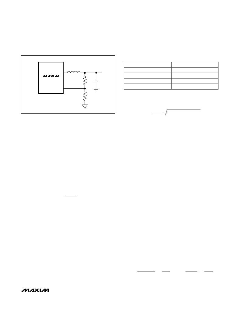
�Table� 1.� FB� Regulation� Voltages�
�PART�
�PRESET� OUTPUT� VOLTAGE�
�LX�
�MAX1927R�
�MAX1928-15�
�0.75V,� Adjustable�
�1.5� V�
�MAX1927R�
�FB�
�R1�
�MAX1928-18�
�MAX1928-25�
�1.8� V�
�2.5� V�
�R2�
�I� RMS� =� � V� OUT� IN� OUT� )�
�� (� V� ?� V�
�R� 1� =� R� 2� � ?� OUT� ?� 1� ?�
�50k� ?�
�Figure� 2.� Setting� the� Adjustable� Output� Voltage�
�Applications� Information�
�Output� Voltage� Selection�
�The� MAX1927/MAX1928� have� preset� output� voltages.�
�In� addition,� the� MAX1927R� has� an� adjustable� output.�
�To� set� the� output� voltage� at� the� preset� voltage,� connect�
�FB� to� the� output.� See� Table� 1� for� a� list� of� the� preset� volt-�
�ages� and� their� corresponding� part� numbers.�
�The� output� voltage� for� the� MAX1927R� is� adjustable�
�from� 0.75V� to� the� input� voltage� by� connecting� FB� to� a�
�resistor-divider� between� the� output� and� GND� (Figure�
�2).� To� determine� the� values� of� the� resistor-divider,� first�
�select� a� value� for� feedback� resistor� R2� between� 5k� ?� to�
�50k� ?� .� R1� is� then� given� by:�
�?� V� ?�
�?� V� FB� ?�
�where� V� FB� is� 0.75V.�
�Input� Capacitor� Selection�
�Capacitor� equivalent� series� resistance� (ESR)� is� a� major�
�contributor� to� input� ripple� in� high-frequency� DC-DC�
�converters.� Ordinary� aluminum-electrolytic� capacitors�
�have� high� ESR� and� should� be� avoided.� Low-ESR� alu-�
�minum� electrolytic� capacitors� are� acceptable� and� rela-�
�tively� inexpensive.� Low-ESR� tantalum� capacitors� or�
�polymer� capacitors� are� better� and� provide� a� compact�
�solution� for� space-constrained� surface-mount� designs.�
�Ceramic� capacitors� have� the� lowest� ESR� overall.�
�following� equation� to� calculate� the� maximum� RMS� input�
�current:�
�I� OUT�
�V� IN�
�Compensation,� Stability,� and�
�Output� Capacitor�
�The� MAX1927/MAX1928� are� externally� compensated�
�with� a� resistor� and� a� capacitor� (see� Figure� 3,� R� C� and�
�C� C� )� in� series� from� COMP� to� GND.� An� additional� capaci-�
�tor� (C� f� )� may� be� required� from� COMP� to� GND� if� high-�
�ESR� output� capacitors� are� used.� The� capacitor� inte-�
�grates� the� current� from� the� transimpedance� amplifier,�
�averaging� output� capacitor� ripple.� This� sets� the� device�
�speed� for� transient� response� and� allows� the� use� of�
�small� ceramic� output� capacitors� because� the� phase-�
�shifted� capacitor� ripple� does� not� disturb� the� current�
�regulation� loop.� The� resistor� sets� the� proportional� gain�
�of� the� output� error� voltage� by� a� factor� g� m� ?� R� C� .�
�Increasing� this� resistor� also� increases� the� sensitivity� of�
�the� control� loop� to� output� ripple.�
�The� resistor� and� capacitor� set� a� compensation� zero�
�that� defines� the� system� ’� s� transient� response.� The� load�
�creates� a� dynamic� pole,� shifting� in� frequency� with�
�changes� in� load.� As� the� load� decreases,� the� pole� fre-�
�quency� decreases.� System� stability� requires� that� the�
�compensation� zero� must� be� placed� to� ensure� adequate�
�phase� margin� (at� least� 30� °� at� unity� gain).� The� following�
�is� a� design� procedure� for� the� compensation� network:�
�1)� Select� an� appropriate� converter� bandwidth� (f� C� )� to�
�stabilize� the� system� while� maximizing� transient�
�response.� This� bandwidth� should� not� exceed� 1/10�
�of� the� switching� frequency.�
�2)� Calculate� the� compensation� capacitor,� C� C� ,� based�
�on� this� bandwidth:�
�?� ?� ?� 1� ?� ?�
�C� C� =� ?�
�?�
�� ?� g� m� �
�?�
�The� input� filter� capacitor� reduces� peak� currents� and�
�noise� at� the� input� voltage� source.� Connect� a� low-ESR�
�bulk� capacitor� (� ≥� 10μF� typ)� to� the� input.� Select� this� bulk�
�capacitor� to� meet� the� input� ripple� requirements� and�
�voltage� rating� rather� than� capacitance� value.� Use� the�
�For� the� MAX1927:�
�V� OUT�
�?� ?�
�?� I� OUT� (� MAX� )� ?� ?� R� CS� ?� ?�
�R� 2� ?� ?� 1� ?�
�R� 1� +� R� 2� ?� ?� ?� 2� π� f� C� ?� ?�
�_______________________________________________________________________________________�
�9�
�相关PDF资料 |
PDF描述 |
|---|---|
| ESC30DRYN | CONN EDGECARD 60POS DIP .100 SLD |
| SCRH64B-471 | INDUCTOR SMD 470UH 0.20A 1KHZ |
| ICL7660ISA+T | IC REG MULTI CONFIG 20MA 8SOIC |
| SCRH64B-391 | INDUCTOR SMD 390UH 0.22A 1KHZ |
| ESC30DRYH | CONN EDGECARD 60POS DIP .100 SLD |
相关代理商/技术参数 |
参数描述 |
|---|---|
| MAX1927REUB-TG05 | 功能描述:直流/直流开关转换器 800mA PWM Step-Down DC/DC Converter RoHS:否 制造商:STMicroelectronics 最大输入电压:4.5 V 开关频率:1.5 MHz 输出电压:4.6 V 输出电流:250 mA 输出端数量:2 最大工作温度:+ 85 C 安装风格:SMD/SMT |
| MAX1927SEUB | 功能描述:直流/直流开关转换器 RoHS:否 制造商:STMicroelectronics 最大输入电压:4.5 V 开关频率:1.5 MHz 输出电压:4.6 V 输出电流:250 mA 输出端数量:2 最大工作温度:+ 85 C 安装风格:SMD/SMT |
| MAX1927SEUB-T | 功能描述:直流/直流开关转换器 RoHS:否 制造商:STMicroelectronics 最大输入电压:4.5 V 开关频率:1.5 MHz 输出电压:4.6 V 输出电流:250 mA 输出端数量:2 最大工作温度:+ 85 C 安装风格:SMD/SMT |
| MAX1928EUB15 | 功能描述:直流/直流开关转换器 800mA PWM Step-Down DC/DC Converter RoHS:否 制造商:STMicroelectronics 最大输入电压:4.5 V 开关频率:1.5 MHz 输出电压:4.6 V 输出电流:250 mA 输出端数量:2 最大工作温度:+ 85 C 安装风格:SMD/SMT |
| MAX1928EUB15+ | 功能描述:直流/直流开关转换器 800mA PWM Step-Down DC/DC Converter RoHS:否 制造商:STMicroelectronics 最大输入电压:4.5 V 开关频率:1.5 MHz 输出电压:4.6 V 输出电流:250 mA 输出端数量:2 最大工作温度:+ 85 C 安装风格:SMD/SMT |
发布紧急采购,3分钟左右您将得到回复。