- 您现在的位置:买卖IC网 > PDF目录383343 > MAX1960 (Maxim Integrated Products, Inc.) 2.35V to 5.5V, 0.5% Accurate, 1MHz PWM Step-Down Controllers with Voltage Margining PDF资料下载
参数资料
| 型号: | MAX1960 |
| 厂商: | Maxim Integrated Products, Inc. |
| 英文描述: | 2.35V to 5.5V, 0.5% Accurate, 1MHz PWM Step-Down Controllers with Voltage Margining |
| 中文描述: | 2.35V至5.5V、0.5%精度、1MHz PWM降压型控制器,带有电压裕量控制 |
| 文件页数: | 13/29页 |
| 文件大小: | 455K |
| 代理商: | MAX1960 |
第1页第2页第3页第4页第5页第6页第7页第8页第9页第10页第11页第12页当前第13页第14页第15页第16页第17页第18页第19页第20页第21页第22页第23页第24页第25页第26页第27页第28页第29页
Inductor operating point.
This choice provides
tradeoffs between size, transient response, and effi-
ciency. Choosing higher inductance values results
in lower inductor ripple current, lower peak current,
lower switching losses, and, therefore, higher effi-
ciency at the cost of slower transient response and
larger size. Choosing lower inductance values
results in large ripple currents, smaller size, and
poorer efficiency, but have faster transient response.
Setting the Output Voltage
The MAX1961 has four output voltage presets selected
by SEL. Table 2 shows how each of the preset voltages
are selected. The MAX1962 also has four preset output
voltages, but also is adjustable down to 0.8V. To use the
preset voltages on the MAX1962, FB must be connected
to V
DD
. SEL then selects the output voltage as shown in
Table 2.
Both the MAX1960/MAX1962 feature an adjustable out-
put that can be set down to 0.8V. To set voltages greater
than 0.8V, Connect FB to a resistor-divider from the out-
put (Figures 9 and 11). Use a resistor up to 10k
for R2
and select R1 according to the following equation:
where the feedback threshold, V
FB
= 0.8V, and V
OUT
is
the output voltage.
Input Voltage Range
The MAX1960/MAX1961/MAX1962 have an input volt-
age range of 2.35V to 5.5V but cannot operate at both
extremes with one application circuit. The standard
charge-pump doubler application circuit operates with
an input range of 2.7V to 5.5V (Figures 9, 10, and 11).
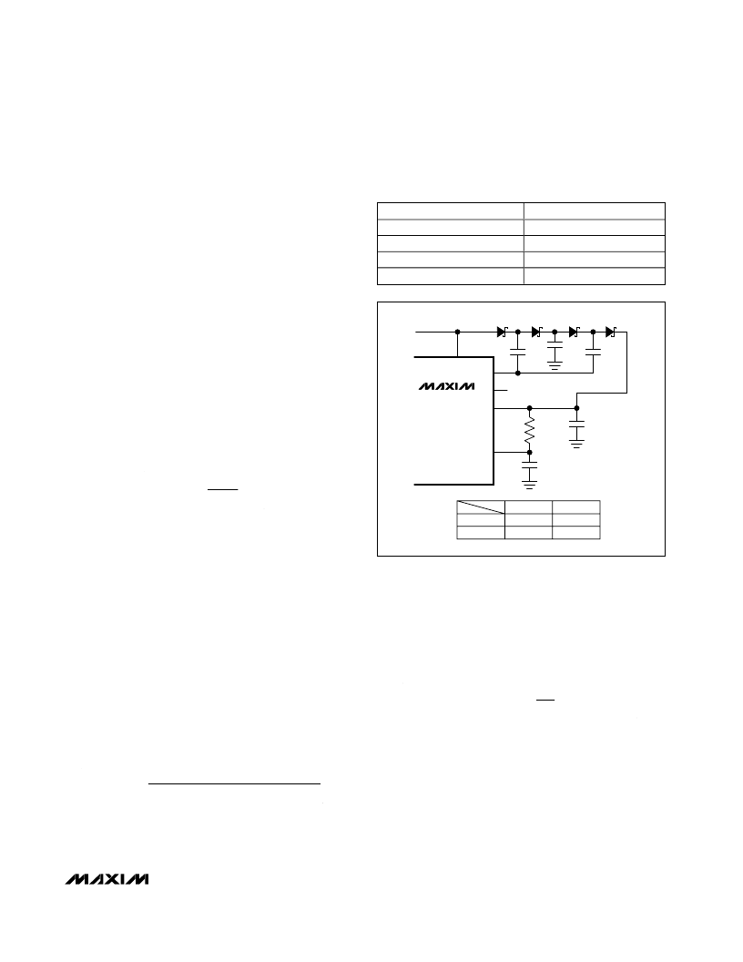
In order to operate down to 2.35V, the charge pump
must be configured as a tripler. This circuit, however,
limits the maximum input voltage to 3.6V. The schematic
for the tripler charge pump is shown in Figure 2. Note
that the flying capacitor between C+ and C- has been
removed and C+ is not connected.
Inductor Selection
Determine an appropriate inductor value with the fol-
lowing equation:
The inductor current ripple, LIR, is the ratio of peak-to-
peak inductor ripple current to the average continuous
inductor current. An LIR between 20% and 40% pro-
vides a good compromise between efficiency and
economy. Choose a low-loss inductor having the lowest
possible DC resistance. Ferrite core type inductors are
often the best choice for performance. The inductor
saturation current rating must exceed I
PEAK
:
Setting the Current Limit
Lossless Current Limit (MAX1960/MAX1961)
The MAX1960/MAX1961 use the low-side MOSFET
’
s on-
resistance (R
DS(ON)
) for current sensing. This method of
current limit sets the maximum value of the inductor
’
s
“
valley
”
current (Figure 3). If the inductor current is higher
than the valley current-limit setting at the end of the
clock period, the controller skips the DH pulse. When
the first current-limit event is detected, the controller initi-
I
I
LIR
2
I
PEAK
LOAD MAX
LOAD MAX
×
(
)
(
)
=
+
L
V
V
V
V
f
LIR
I
OUT
IN
×
OUT
×
IN
OSC
LOAD MAX
=
×
×
(
)
-
R
R
V
V
OUT
FB
1
2
1
=
×
-
M
2.35V to 5.5V, 0.5% Accurate, 1MHz PWM
Step-Down Controllers with Voltage Margining
______________________________________________________________________________________
13
PRESET OUTPUT VOLTAGE
1.5V
1.8V
2.5V
3.3V
SEL
GND
REF
No connection
V
DD
Table 2. Preset Voltages
—
MAX1961/MAX1962
MAX1960/
MAX1961/
MAX1962
C10
C11
C12
C6
D2
D3
D4
D5
R5
10
C4
1
μ
F
V
CC
C-
C+
V
DD
AV
DD
C10, C11, C12
C6
500kHz
1
μ
F
4.7
μ
F
1MHz
0.47
μ
F
2.2
μ
F
Figure 2. Tripler Charge-Pump Configuration.
相关PDF资料 |
PDF描述 |
|---|---|
| MAX1960EEP | 2.35V to 5.5V, 0.5% Accurate, 1MHz PWM Step-Down Controllers with Voltage Margining |
| MAX1961 | 2.35V to 5.5V, 0.5% Accurate, 1MHz PWM Step-Down Controllers with Voltage Margining |
| MAX1962 | 2.35V to 5.5V, 0.5% Accurate, 1MHz PWM Step-Down Controllers with Voltage Margining |
| MAX1962EEP | 2.35V to 5.5V, 0.5% Accurate, 1MHz PWM Step-Down Controllers with Voltage Margining |
| MAX19700 | 10-Bit, 45Msps, Ultra-Low-Power Analog Front-End |
相关代理商/技术参数 |
参数描述 |
|---|---|
| MAX1960EEP | 功能描述:DC/DC 开关控制器 RoHS:否 制造商:Texas Instruments 输入电压:6 V to 100 V 开关频率: 输出电压:1.215 V to 80 V 输出电流:3.5 A 输出端数量:1 最大工作温度:+ 125 C 安装风格: 封装 / 箱体:CPAK |
| MAX1960EEP+ | 功能描述:DC/DC 开关控制器 1MHz PWM Step-Down RoHS:否 制造商:Texas Instruments 输入电压:6 V to 100 V 开关频率: 输出电压:1.215 V to 80 V 输出电流:3.5 A 输出端数量:1 最大工作温度:+ 125 C 安装风格: 封装 / 箱体:CPAK |
| MAX1960EEP+T | 功能描述:DC/DC 开关控制器 1MHz PWM Step-Down RoHS:否 制造商:Texas Instruments 输入电压:6 V to 100 V 开关频率: 输出电压:1.215 V to 80 V 输出电流:3.5 A 输出端数量:1 最大工作温度:+ 125 C 安装风格: 封装 / 箱体:CPAK |
| MAX1960EEP-T | 功能描述:DC/DC 开关控制器 RoHS:否 制造商:Texas Instruments 输入电压:6 V to 100 V 开关频率: 输出电压:1.215 V to 80 V 输出电流:3.5 A 输出端数量:1 最大工作温度:+ 125 C 安装风格: 封装 / 箱体:CPAK |
| MAX1960EVKIT | 功能描述:电源管理IC开发工具 Evaluation Kit for the MAX1960 MAX1961 MAX1962 RoHS:否 制造商:Maxim Integrated 产品:Evaluation Kits 类型:Battery Management 工具用于评估:MAX17710GB 输入电压: 输出电压:1.8 V |
发布紧急采购,3分钟左右您将得到回复。