- 您现在的位置:买卖IC网 > PDF目录383343 > MAX1961 (Maxim Integrated Products, Inc.) 2.35V to 5.5V, 0.5% Accurate, 1MHz PWM Step-Down Controllers with Voltage Margining PDF资料下载
参数资料
| 型号: | MAX1961 |
| 厂商: | Maxim Integrated Products, Inc. |
| 英文描述: | 2.35V to 5.5V, 0.5% Accurate, 1MHz PWM Step-Down Controllers with Voltage Margining |
| 中文描述: | 2.35V至5.5V、0.5%精度、1MHz PWM降压型控制器,带有电压裕量控制 |
| 文件页数: | 10/29页 |
| 文件大小: | 455K |
| 代理商: | MAX1961 |
第1页第2页第3页第4页第5页第6页第7页第8页第9页当前第10页第11页第12页第13页第14页第15页第16页第17页第18页第19页第20页第21页第22页第23页第24页第25页第26页第27页第28页第29页
M
Detailed Description
The MAX1960/MAX1961/MAX1962 are high-current,
high-efficiency voltage-mode step-down DC-DC con-
trollers that operate from 2.35V to 5.5V input and gener-
ate adjustable voltages down to 0.8V at up to 20A. An
on-chip charge pump generates a regulated 5V for dri-
ving a variety of external N-channel MOSFETs.
Constant frequency PWM operation and external syn-
chronization make these controllers suitable for telecom
and datacom applications. The operating frequency is
programmed externally to either 500kHz or 1MHz, or
from 450kHz to 1.2MHz with an external clock. A clock
output is provided to synchronize another converter for
180
°
out-of-phase operation.
A high closed-loop bandwidth provides excellent tran-
sient response for applications with dynamic loads.
Internal Charge Pump
An on-chip regulated charge pump develops 5V at
50mA (max) with input voltages as low as 2.35V. The
output of this charge pump provides power for the
internal circuitry, bias for the low-side driver (DL), and
the bias for the boost diode, which supplies the high-
side MOSFET gate driver (DH). The charge pump is
synchronized with the DL driver signal and operates at
1/2 the PWM frequency.
The external MOSFET gate charge is the dominant load
for the charge pump and is proportional to the PWM
switching frequency. The charge pump must supply
chip-operating current plus adequate gate current for
both MOSFETs at the selected operating frequency.
The required charge-pump output current is given by
the formula:
I
TOTAL
= I
AVDD
+ f
OSC
(Q
G1
+ Q
G2
)
where I
AVDD
is the current supplied to the IC through
AV
DD
(typically 2mA), f
OSC
is the PWM switching
frequency, Q
G1
is the gate charge of the high-side
MOSFET, and Q
G2
is the gate charge of the low-side
MOSFET. The MOSFETs must be chosen such that
I
TOTAL
does not exceed 50mA. For example, with 1MHz
operation, Q
G1
+ Q
G2
should be less than 48nC.
Voltage Margining and Shutdown
The voltage-margining feature on the MAX1960/
MAX1961 shifts the output voltage up or down by 4%.
This is useful for the automatic testing of systems at high
and low supply conditions to find potential hardware fail-
ures. CTL1 and CTL2 control voltage margining as out-
lined in Table 1.
A shutdown feature is included on all three parts, which
stops switching the output drivers and the charge
pump, reducing the supply current to less than 15μA.
For the MAX1962, drive EN high for normal operation,
or low for shutdown. For the MAX1960/MAX1961, drive
both CTL1 and CTL2 high for normal operation, or drive
CTL1 and CTL2 low for shutdown. For a simple
enable/shutdown function with no voltage margining,
connect CTL1 and CTL2 together and drive as one
input.
2.35V to 5.5V, 0.5% Accurate, 1MHz PWM
Step-Down Controllers with Voltage Margining
10
______________________________________________________________________________________
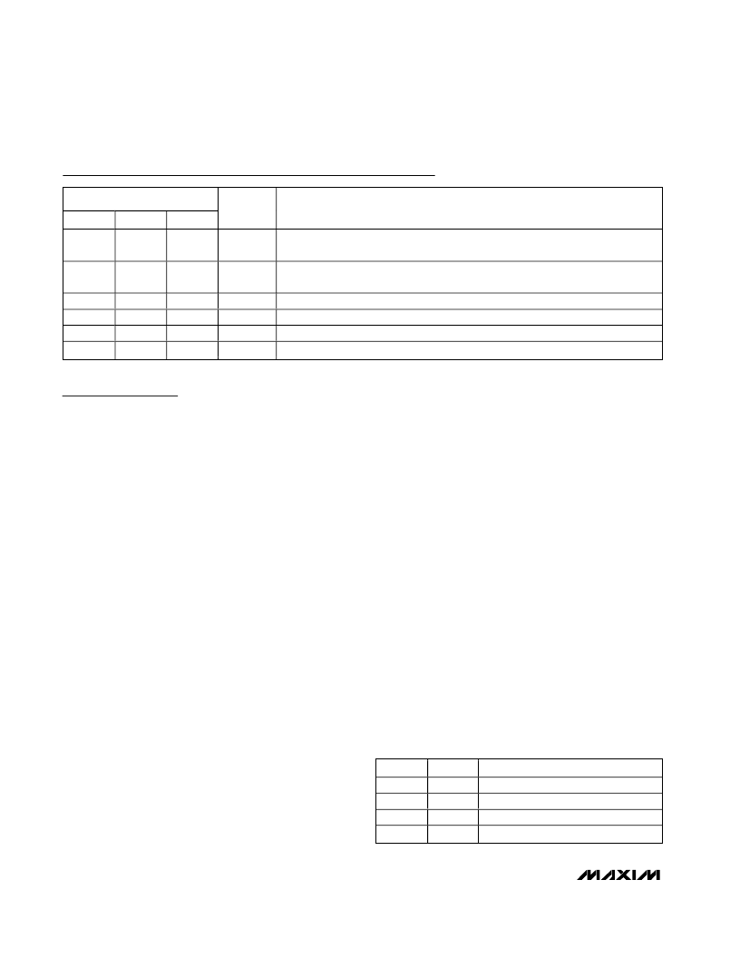
Pin Description (continued)
PIN
MAX1960 MAX1961 MAX1962
NAME
FUNCTION
15
15
15
C-
Charge-Pump Flying Capacitor Negative Connection. Use a 0.47μF ceramic
capacitor at 1MHz, and 1μF between 450kHz and 950kHz.
16
16
16
C+
Charge-Pump Flying Capacitor Positive Connection. Use a 0.47μF ceramic
capacitor at 1MHz and 1μF between 450kHz and 950kHz.
17
18
19
20
17
18
19
20
17
18
19
20
V
CC
BST
DH
LX
Input Supply to Charge Pump
Boost Capacitor Connection. Connect a 0.1μF ceramic capacitor from BST to LX.
High-Side MOSFET Gate-Driver Output. DH is low in shutdown.
Inductor Connection
CTL1
High
High
Low
Low
CTL2
High
Low
High
Low
FUNCTION
Normal operation
+4% output-voltage shift
-4% output-voltage shift
Shutdown
Table 1. Voltage Margining Truth Table
相关PDF资料 |
PDF描述 |
|---|---|
| MAX1962 | 2.35V to 5.5V, 0.5% Accurate, 1MHz PWM Step-Down Controllers with Voltage Margining |
| MAX1962EEP | 2.35V to 5.5V, 0.5% Accurate, 1MHz PWM Step-Down Controllers with Voltage Margining |
| MAX19700 | 10-Bit, 45Msps, Ultra-Low-Power Analog Front-End |
| MAX19705 | 10-Bit, 45Msps, Ultra-Low-Power Analog Front-End |
| MAX19706 | 10-Bit, 45Msps, Ultra-Low-Power Analog Front-End |
相关代理商/技术参数 |
参数描述 |
|---|---|
| MAX1961EEP | 功能描述:DC/DC 开关控制器 RoHS:否 制造商:Texas Instruments 输入电压:6 V to 100 V 开关频率: 输出电压:1.215 V to 80 V 输出电流:3.5 A 输出端数量:1 最大工作温度:+ 125 C 安装风格: 封装 / 箱体:CPAK |
| MAX1961EEP+ | 功能描述:DC/DC 开关控制器 1MHz PWM Step-Down RoHS:否 制造商:Texas Instruments 输入电压:6 V to 100 V 开关频率: 输出电压:1.215 V to 80 V 输出电流:3.5 A 输出端数量:1 最大工作温度:+ 125 C 安装风格: 封装 / 箱体:CPAK |
| MAX1961EEP+T | 功能描述:DC/DC 开关控制器 1MHz PWM Step-Down RoHS:否 制造商:Texas Instruments 输入电压:6 V to 100 V 开关频率: 输出电压:1.215 V to 80 V 输出电流:3.5 A 输出端数量:1 最大工作温度:+ 125 C 安装风格: 封装 / 箱体:CPAK |
| MAX1961EEP-T | 功能描述:DC/DC 开关控制器 RoHS:否 制造商:Texas Instruments 输入电压:6 V to 100 V 开关频率: 输出电压:1.215 V to 80 V 输出电流:3.5 A 输出端数量:1 最大工作温度:+ 125 C 安装风格: 封装 / 箱体:CPAK |
| MAX1962EEP | 功能描述:DC/DC 开关控制器 RoHS:否 制造商:Texas Instruments 输入电压:6 V to 100 V 开关频率: 输出电压:1.215 V to 80 V 输出电流:3.5 A 输出端数量:1 最大工作温度:+ 125 C 安装风格: 封装 / 箱体:CPAK |
发布紧急采购,3分钟左右您将得到回复。