- 您现在的位置:买卖IC网 > PDF目录14390 > MAX1972EEE+ (Maxim Integrated Products)IC REG BUCK SYNC 0.75A DL 16QSOP PDF资料下载
参数资料
| 型号: | MAX1972EEE+ |
| 厂商: | Maxim Integrated Products |
| 文件页数: | 11/21页 |
| 文件大小: | 0K |
| 描述: | IC REG BUCK SYNC 0.75A DL 16QSOP |
| 产品培训模块: | Lead (SnPb) Finish for COTS Obsolescence Mitigation Program |
| 标准包装: | 100 |
| 类型: | 降压(降压) |
| 输出类型: | 两者兼有 |
| 输出数: | 2 |
| 输出电压: | 1.5V,1.8V,2.5V,3.3V,可调 |
| 输入电压: | 2.6 V ~ 5.5 V |
| PWM 型: | 电流模式 |
| 频率 - 开关: | 1.4MHz |
| 电流 - 输出: | 750mA |
| 同步整流器: | 是 |
| 工作温度: | -40°C ~ 85°C |
| 安装类型: | 表面贴装 |
| 封装/外壳: | 16-SSOP(0.154",3.90mm 宽) |
| 包装: | 管件 |
| 供应商设备封装: | 16-QSOP |
�� �
�
�Dual,� 180°� Out-of-Phase,� 1.4MHz,� 750mA� Step-�
�Down� Regulator� with� POR� and� RSI/PFO�
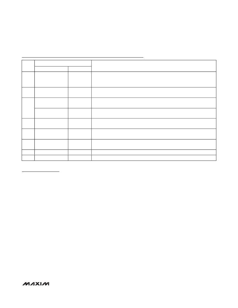
�Pin� Description� (continued)�
�PIN�
�NAME�
�MAX1970/MAX1972�
�MAX1971�
�FUNCTION�
�Active-Low� Power-On� Reset� Output.� Open-drain� output� goes� high� 16.6ms�
�9�
�POR�
�POR�
�(MAX1970)� or� 175ms� (MAX1971� or� MAX1972)� after� both� outputs� reach� 92%� of�
�nominal� value,� and� RSI� (MAX1971� only)� is� low.�
�10�
�11�
�12�
�13�
�14�
�15�
�16�
�EN�
�PFO�
�—�
�FBSEL2�
�FBSEL1�
�IN�
�LX2�
�PGND�
�EN�
�—�
�RSI�
�FBSEL2�
�FBSEL1�
�IN�
�LX2�
�PGND�
�Enable� Input.� Drive� high� to� turn� on� both� OUT1� and� OUT2.� Drive� low� to� place� the�
�device� in� shutdown.�
�Power-Fail� Output.� Open-drain� output� goes� high� when� V� CC� drops� below� 3.94V.�
�Useful� for� detecting� a� valid� USB� input� voltage.�
�Noninverting� Reset� Input.� Causes� POR� to� go� low� when� RSI� is� high.� Allows� POR� to�
�go� high� 175ms� after� RSI� falls,� if� outputs� are� in� regulation.�
�Regulator� 2� Feedback� Select.� Connect� to� V� CC� to� set� V� OUT2� to� 2.5V.� Connect� to�
�GND� to� set� V� OUT2� to� 1.5V.� Leave� unconnected� to� use� external� feedback� resistors.�
�Regulator� 1� Feedback� Select.� Connect� to� V� CC� to� set� V� OUT1� to� 3.3V.� Connect� to�
�GND� to� set� V� OUT1� to� 1.8V.� Leave� unconnected� to� use� external� feedback� resistors.�
�Power-Supply� Voltage.� Input� range� from� 2.6V� to� 5.5V.� Bypass� with� 10μF� capacitor�
�to� PGND.�
�Inductor� Connection� 2.� Connect� an� inductor� between� LX2� and� OUT2.�
�Power� Ground�
�Detailed� Description�
�The� MAX1970/MAX1971/MAX1972� are� dual-output,�
�fixed-frequency,� current-mode,� PWM,� step-down�
�DC-DC� converters.� The� MAX1970� and� MAX1972� switch�
�at� 1.4� MHz� while� the� MAX1971� switches� at� 700kHz.� The�
�two� converters� on� each� IC� switch� 180°� out� of� phase�
�with� each� other� to� reduce� input� ripple� current.� The�
�high-switching� frequency� allows� use� of� smaller� capaci-�
�tors� for� filtering� and� decoupling.� Internal� synchronous�
�rectifiers� improve� efficiency� and� eliminate� the� typical�
�Schottky� freewheeling� diode.� The� on-resistances� of� the�
�internal� MOSFETs� are� used� to� sense� the� switch� cur-�
�rents� for� controlling� and� protecting� the� MOSFETs,� elimi-�
�nating� current-sensing� resistors� to� further� improve�
�efficiency� and� cost.�
�The� input� voltage� range� is� 2.6V� to� 5.5V.� Each� converter�
�has� a� three-mode� feedback� input.� Internally,� OUT1� is�
�set� to� either� 3.3V� or� 1.8V,� and� OUT2� to� 2.5V� or� 1.5V� by�
�connecting� FBSEL1� and� FBSEL2� to� V� CC� or� GND,�
�respectively.� When� FBSEL1� or� FBSEL2� are� floating,�
�each� output� can� be� set� to� any� voltage� between� 1.2V�
�and� V� IN� through� an� external� resistive� divider.� Having� an�
�output� below� 1.2V� is� also� possible� (see� the� Output�
�Voltage� Selection� section).�
�DC-DC� Controller�
�The� MAX1970/MAX1971/MAX1972� family� of� step-down�
�converters� uses� a� pulse-width-modulating� (PWM)� current-�
�mode� control� scheme.� The� heart� of� the� current-mode�
�PWM� controller� is� an� open-loop� comparator� that� com-�
�pares� the� integrated� voltage-feedback� signal� against�
�the� sum� of� the� amplified� current-sense� signal� and� the�
�slope� compensation� ramp.� At� each� rising� edge� of� the�
�internal� clock,� the� internal� high-side� MOSFET� turns� on�
�until� the� PWM� comparator� trips.� During� this� on� time,�
�current� ramps� up� through� the� inductor,� sourcing� cur-�
�rent� to� the� output� and� storing� energy� in� a� magnetic�
�field.� The� current-mode� feedback� system� regulates� the�
�peak� inductor� current� as� a� function� of� the� output� volt-�
�age� error� signal.� Since� the� average� inductor� current� is�
�nearly� the� same� as� the� peak� inductor� current� (assum-�
�ing� that� the� inductor� value� is� relatively� high� to� minimize�
�ripple� current),� the� circuit� acts� as� a� switch-mode�
�transconductance� amplifier.� It� pushes� the� output� LC� filter�
�pole,� normally� found� in� a� voltage-mode� PWM,� to� a� higher�
�frequency.� To� preserve� inner� loop� stability� and� eliminate�
�inductor� stair� casing,� a� slope-compensation� ramp� is�
�summed� into� the� main� PWM� comparator.� During� the�
�second� half� of� the� cycle,� the� internal� high-side� MOSFET�
�______________________________________________________________________________________�
�11�
�相关PDF资料 |
PDF描述 |
|---|---|
| ESC22DRAH | CONN EDGECARD 44POS R/A .100 SLD |
| MAX6467US29D3+T | IC MPU/RESET CIRC 2.925V SOT143 |
| LQW15AN47NG00D | INDUCTOR |
| MAX643ACSA+ | IC REG BOOST 15V/ADJ 1.5A 8SOIC |
| RBM28DRYH | CONN EDGECARD 56POS DIP .156 SLD |
相关代理商/技术参数 |
参数描述 |
|---|---|
| MAX1972EEE+ | 功能描述:直流/直流开关调节器 Dual 180 Out 1.4MHz 750mA Step-Down RoHS:否 制造商:International Rectifier 最大输入电压:21 V 开关频率:1.5 MHz 输出电压:0.5 V to 0.86 V 输出电流:4 A 输出端数量: 最大工作温度: 安装风格:SMD/SMT 封装 / 箱体:PQFN 4 x 5 |
| MAX1972EEE+T | 功能描述:直流/直流开关调节器 Dual 180 Out 1.4MHz 750mA Step-Down RoHS:否 制造商:International Rectifier 最大输入电压:21 V 开关频率:1.5 MHz 输出电压:0.5 V to 0.86 V 输出电流:4 A 输出端数量: 最大工作温度: 安装风格:SMD/SMT 封装 / 箱体:PQFN 4 x 5 |
| MAX1972EEE-G05 | 功能描述:电流型 PWM 控制器 RoHS:否 制造商:Texas Instruments 开关频率:27 KHz 上升时间: 下降时间: 工作电源电压:6 V to 15 V 工作电源电流:1.5 mA 输出端数量:1 最大工作温度:+ 105 C 安装风格:SMD/SMT 封装 / 箱体:TSSOP-14 |
| MAX1972EEE-T | 功能描述:直流/直流开关调节器 RoHS:否 制造商:International Rectifier 最大输入电压:21 V 开关频率:1.5 MHz 输出电压:0.5 V to 0.86 V 输出电流:4 A 输出端数量: 最大工作温度: 安装风格:SMD/SMT 封装 / 箱体:PQFN 4 x 5 |
| MAX1972EEE-TG05 | 功能描述:电流型 PWM 控制器 RoHS:否 制造商:Texas Instruments 开关频率:27 KHz 上升时间: 下降时间: 工作电源电压:6 V to 15 V 工作电源电流:1.5 mA 输出端数量:1 最大工作温度:+ 105 C 安装风格:SMD/SMT 封装 / 箱体:TSSOP-14 |
发布紧急采购,3分钟左右您将得到回复。