- 您现在的位置:买卖IC网 > PDF目录15038 > MAX1992ETG+ (Maxim Integrated Products)IC REG CTRLR BUCK PWM CM 24-TQFN PDF资料下载
参数资料
| 型号: | MAX1992ETG+ |
| 厂商: | Maxim Integrated Products |
| 文件页数: | 16/36页 |
| 文件大小: | 0K |
| 描述: | IC REG CTRLR BUCK PWM CM 24-TQFN |
| 标准包装: | 75 |
| 系列: | Quick-PWM™ |
| PWM 型: | 电流模式 |
| 输出数: | 1 |
| 频率 - 最大: | 600kHz |
| 占空比: | 100% |
| 电源电压: | 4.5 V ~ 5.5 V |
| 降压: | 是 |
| 升压: | 无 |
| 回扫: | 无 |
| 反相: | 无 |
| 倍增器: | 无 |
| 除法器: | 无 |
| Cuk: | 无 |
| 隔离: | 无 |
| 工作温度: | -40°C ~ 85°C |
| 封装/外壳: | 24-WFQFN 裸露焊盘 |
| 包装: | 管件 |
第1页第2页第3页第4页第5页第6页第7页第8页第9页第10页第11页第12页第13页第14页第15页当前第16页第17页第18页第19页第20页第21页第22页第23页第24页第25页第26页第27页第28页第29页第30页第31页第32页第33页第34页第35页第36页
�� �
�
�Quick-PWM� Step-Down� Controllers� with� Inductor�
�Saturation� Protection� and� Dynamic� Output� Voltages�
�Detailed� Description�
�The� MAX1992/MAX1993� buck� controllers� are� ideal� for�
�low-voltage� power� supplies� for� notebook� computers.�
�Maxim’s� proprietary� Quick-PWM� pulse-width� modulator�
�in� the� MAX1992/MAX1993� is� designed� for� handling� fast�
�load� steps� while� maintaining� a� relatively� constant� oper-�
�ating� frequency� and� inductor� operating� point� over� a�
�wide� range� of� input� voltages.� The� Quick-PWM� architec-�
�ture� circumvents� the� poor� load-transient� timing� prob-�
�lems� of� fixed-frequency� current-mode� PWMs� while�
�avoiding� the� problems� caused� by� widely� varying�
�switching� frequencies� in� conventional� constant-on-time�
�and� constant-off-time� PWM� schemes.�
�See� Table� 1� for� component� selections� and� Table� 2� for� a�
�list� of� component� suppliers.�
�+5V� Bias� Supply� (V� CC� and� V� DD� )�
�The� MAX1992/MAX1993� require� an� external� 5V� bias�
�supply� in� addition� to� the� battery.� Typically,� this� 5V� bias�
�supply� is� the� notebook’s� 95%-efficient� 5V� system� sup-�
�ply.� Keeping� the� bias� supply� external� to� the� IC� improves�
�efficiency� and� eliminates� the� cost� associated� with� the� 5V�
�linear� regulator� that� would� otherwise� be� needed� to� sup-�
�ply� the� PWM� circuit� and� gate� drivers.� If� stand-alone�
�capability� is� needed,� the� 5V� supply� can� be� generated�
�with� an� external� linear� regulator� such� as� the� MAX1615.�
�The� 5V� bias� supply� must� provide� V� CC� (PWM� controller)�
�and� V� DD� (gate-drive� power),� so� the� maximum� current�
�drawn� is:�
�I� BIAS� =� I� CC� +� f� SW� (Q� G(LOW)� +� Q� G(HIGH)� )�
�=� 2mA� to� 20mA� (typ)�
�where� I� CC� is� 550μA� (typ),� f� SW� is� the� switching� frequency,�
�and� Q� G(LOW)� and� Q� G(HIGH)� are� the� MOSFET� data�
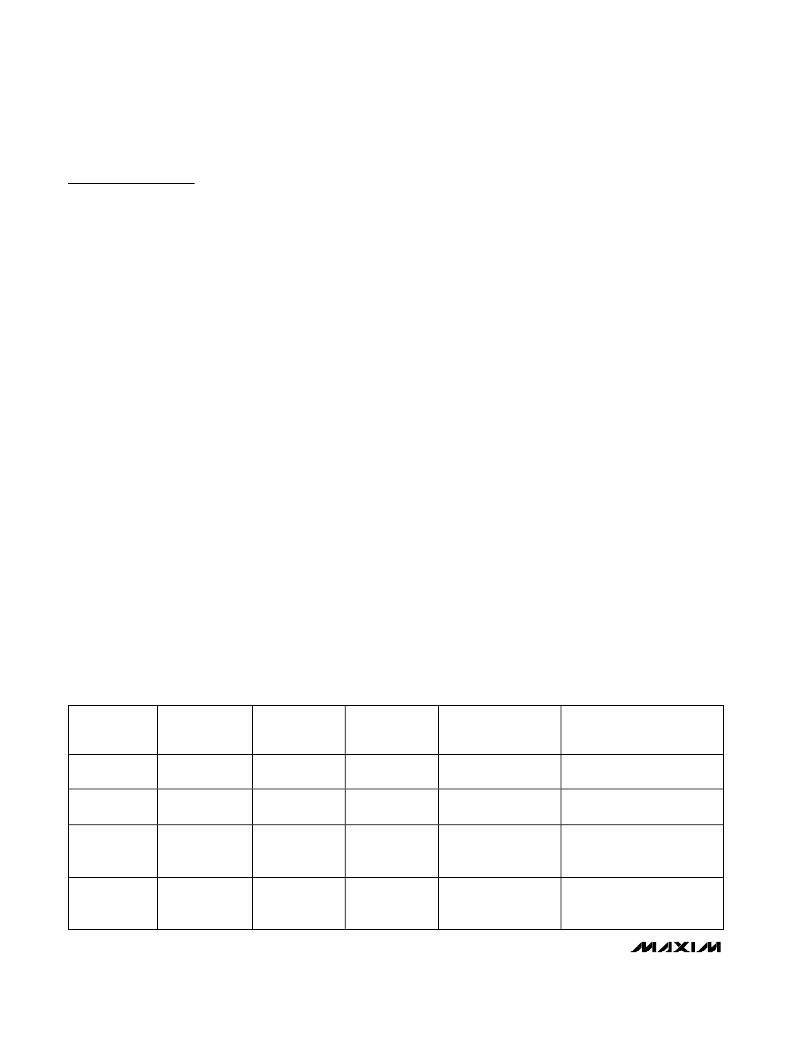
�Table� 3.� Approximate� K-Factor� Errors�
�sheet’s� total� gate-charge� specification� limits� at� V� GS� =� 5V.�
�The� V+� battery� input� and� 5V� bias� inputs� (V� CC� and� V� DD� )�
�can� be� connected� together� if� the� input� source� is� a� fixed�
�4.5V� to� 5.5V� supply.� If� the� 5V� bias� supply� is� powered�
�up� prior� to� the� battery� supply,� the� enable� signal� (� SHDN�
�going� from� low� to� high)� must� be� delayed� until� the� bat-�
�tery� voltage� is� present� in� order� to� ensure� startup.�
�Free-Running� Constant-On-Time� PWM�
�Controller� with� Input� Feed� Forward�
�The� Quick-PWM� control� architecture� is� a� pseudofixed-�
�frequency,� constant� on-time,� current-mode� regulator�
�with� voltage� feed� forward� (Figure� 2).� This� architecture�
�relies� on� the� output� filter� capacitor’s� ESR� to� act� as� a�
�current-sense� resistor,� so� the� output� ripple� voltage� pro-�
�vides� the� PWM� ramp� signal.� The� control� algorithm� is�
�simple:� the� high-side� switch� on-time� is� determined� sole-�
�ly� by� a� one-shot� whose� pulse� width� is� inversely� propor-�
�tional� to� input� voltage� and� directly� proportional� to�
�output� voltage.� Another� one-shot� sets� a� minimum� off-�
�time� (400ns� typ).� The� on-time� one-shot� is� triggered� if�
�the� error� comparator� is� low,� the� low-side� switch� current�
�is� below� the� valley� current-limit� threshold,� and� the� mini-�
�mum� off-time� one-shot� has� timed� out.�
�On-Time� One-Shot� (TON)�
�The� heart� of� the� PWM� core� is� the� one-shot� that� sets� the�
�high-side� switch� on-time.� This� fast,� low-jitter,� adjustable�
�one-shot� includes� circuitry� that� varies� the� on-time� in�
�response� to� battery� and� output� voltage.� The� high-side�
�switch� on-time� is� inversely� proportional� to� the� battery�
�voltage� as� measured� by� the� V+� input� and� is� proportional�
�to� the� output� voltage:�
�On-time� =� K� (V� OUT� +� 0.075V)� /� V� IN�
�TON� SETTING�
�(kHz)�
�200�
�(TON� =� V� CC� )�
�300�
�(TON� =� open)�
�450�
�(TON� =� REF)�
�600�
�(TON� =� GND)�
�TYPICAL�
�K-FACTOR� (μs)�
�5.0�
�3.3�
�2.2�
�1.7�
�K-FACTOR�
�ERROR� (%)�
�±10�
�±10�
�±12.5�
�±12.5�
�MINIMUM� V� IN�
�AT� V� OUT� =� 2.5V�
�(h� =� 1.5)� (V)�
�3.14�
�3.47�
�4.13�
�5.61�
�TYPICAL�
�APPLICATION�
�4-cell� Li+� notebook�
�4-cell� Li+� notebook�
�3-cell� Li+� notebook�
�+5V� input�
�COMMENTS�
�Use� for� absolute� best� efficiency�
�Considered� mainstream� by�
�current� standards�
�Useful� in� 3-cell� systems� for�
�lighter� loads� than� the� CPU� core�
�or� where� size� is� key�
�Good� operating� point� for�
�compound� buck� designs� or�
�desktop� circuits�
�16�
�______________________________________________________________________________________�
�相关PDF资料 |
PDF描述 |
|---|---|
| MAX1897ETP+ | IC REG CTRLR BUCK PWM 20-TQFN |
| MAX1844ETP+ | IC REG CTRLR BUCK PWM CM 20-TQFN |
| VE-2TY-EX-F4 | CONVERTER MOD DC/DC 3.3V 49.5W |
| MAX1844EEP+ | IC REG CTRLR BUCK PWM CM 20-QSOP |
| UPM1J122MHD | CAP ALUM 1200UF 63V 20% RADIAL |
相关代理商/技术参数 |
参数描述 |
|---|---|
| MAX1992ETG+ | 功能描述:电压模式 PWM 控制器 Step-Down w/Inductor RoHS:否 制造商:Texas Instruments 输出端数量:1 拓扑结构:Buck 输出电压:34 V 输出电流: 开关频率: 工作电源电压:4.5 V to 5.5 V 电源电流:600 uA 最大工作温度:+ 125 C 最小工作温度:- 40 C 封装 / 箱体:WSON-8 封装:Reel |
| MAX1992ETG+T | 功能描述:电压模式 PWM 控制器 Step-Down w/Inductor RoHS:否 制造商:Texas Instruments 输出端数量:1 拓扑结构:Buck 输出电压:34 V 输出电流: 开关频率: 工作电源电压:4.5 V to 5.5 V 电源电流:600 uA 最大工作温度:+ 125 C 最小工作温度:- 40 C 封装 / 箱体:WSON-8 封装:Reel |
| MAX1992ETG-T | 功能描述:电压模式 PWM 控制器 RoHS:否 制造商:Texas Instruments 输出端数量:1 拓扑结构:Buck 输出电压:34 V 输出电流: 开关频率: 工作电源电压:4.5 V to 5.5 V 电源电流:600 uA 最大工作温度:+ 125 C 最小工作温度:- 40 C 封装 / 箱体:WSON-8 封装:Reel |
| MAX1993ETG | 功能描述:电压模式 PWM 控制器 RoHS:否 制造商:Texas Instruments 输出端数量:1 拓扑结构:Buck 输出电压:34 V 输出电流: 开关频率: 工作电源电压:4.5 V to 5.5 V 电源电流:600 uA 最大工作温度:+ 125 C 最小工作温度:- 40 C 封装 / 箱体:WSON-8 封装:Reel |
| MAX1993ETG+ | 功能描述:电压模式 PWM 控制器 Step-Down w/Inductor RoHS:否 制造商:Texas Instruments 输出端数量:1 拓扑结构:Buck 输出电压:34 V 输出电流: 开关频率: 工作电源电压:4.5 V to 5.5 V 电源电流:600 uA 最大工作温度:+ 125 C 最小工作温度:- 40 C 封装 / 箱体:WSON-8 封装:Reel |
发布紧急采购,3分钟左右您将得到回复。