- 您现在的位置:买卖IC网 > PDF目录18709 > MAX2022ETX+D (Maxim Integrated)IC QUADRATURE MODULATOR 36QFN PDF资料下载
参数资料
| 型号: | MAX2022ETX+D |
| 厂商: | Maxim Integrated |
| 文件页数: | 23/26页 |
| 文件大小: | 0K |
| 描述: | IC QUADRATURE MODULATOR 36QFN |
| 标准包装: | 50 |
| 功能: | 调制器 |
| LO 频率: | 1.5GHz ~ 2.5GHz |
| RF 频率: | 1.5GHz ~ 2.5GHz |
| 底噪: | -173.2dBm/Hz |
| 输出功率: | -20.8dBm |
| 电流 - 电源: | 342mA |
| 电源电压: | 4.75 V ~ 5.25 V |
| 测试频率: | 2.14GHz |
| 封装/外壳: | 36-WFQFN 裸露焊盘 |
| 包装: | 管件 |
�� �
�
�MAX2022�
�R� a�
�High-Dynamic-Range,� Direct� Up/�
�Downconversion� 1500MHz� to� 3000MHz�
�Quadrature� Modulator/Demodulator�
�L� d�
�C� a�
�MAX2022�
�I/Q� OUTPUTS�
�L� a�
�C� b�
�L� b�
�C� c�
�L� c�
�R� b�
�C� d�
�C� e�
�EXTERNAL�
�STAGE�
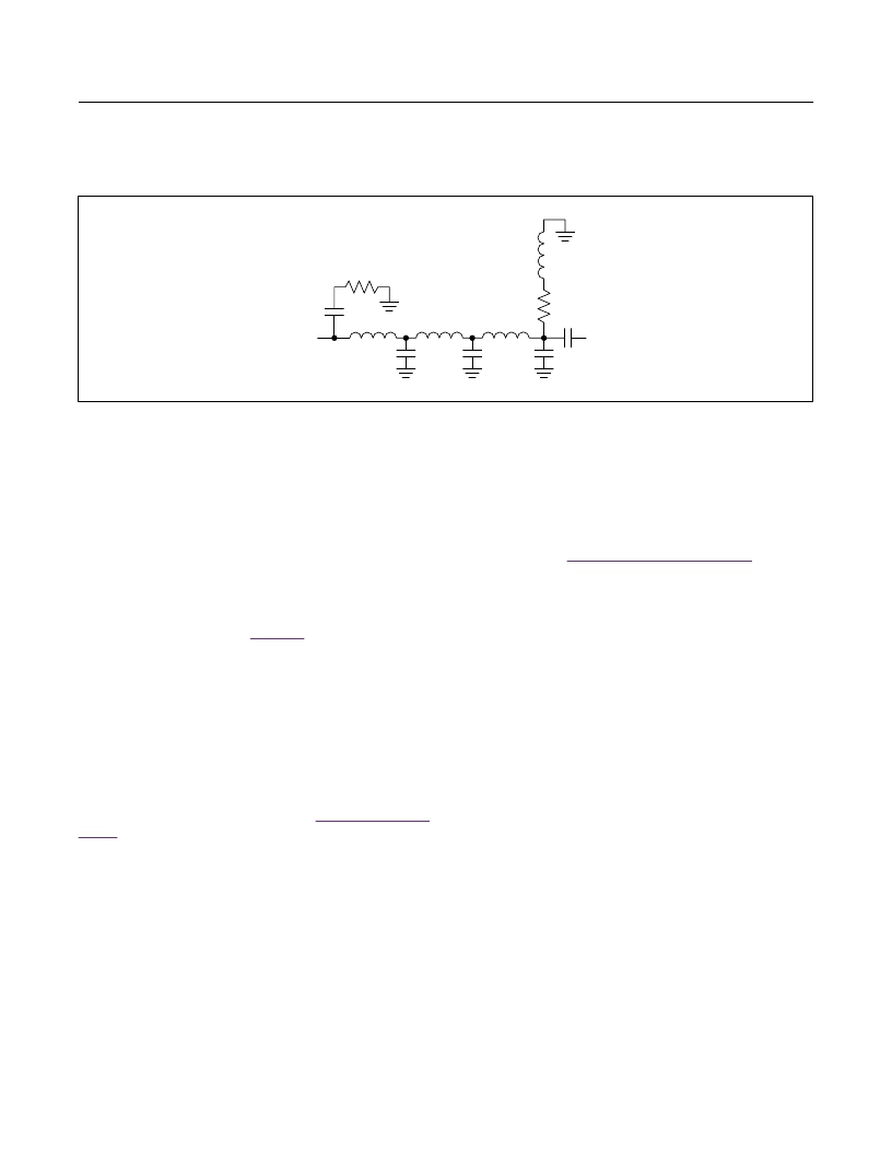
�Figure� 6.� Baseband� Port� Typical� Filtering� and� DC� Return� Network�
�Resistor� R� b� provides� a� DC� return� to� set� the� common-�
�mode� voltage.� In� this� case,� due� to� the� on-chip� circuitry,�
�the� voltage� is� approximately� 0V� DC.� It� can� also� be� used�
�to� reduce� the� load� impedance� of� the� next� stage.� Inductor�
�L� d� can� provide� a� bit� of� high-frequency� gain� peaking� for�
�wideband� IF� systems.� Capacitor� C� e� is� a� DC� block.�
�Typical� values� for� C� a� ,� R� a� ,� L� a� ,� and� C� b� would� be� 1.5pF,�
�50?, � 11nH, � and � 4.7pF, � respectively. � These � values � can �
�change� depending� on� the� LO,� RF,� and� IF� frequencies�
�used.� Resistor� R� b� is in the 50? to 200? range.�
�The� circuitry� presented� in� Figure 6� does� not� allow� for�
�LO� leakage� at� RF� port� nulling.� Depending� on� the� LO� at�
�RF� leakage� requirement,� a� trim� voltage� may� need� to� be�
�introduced� on� the� baseband� ports� to� null� the� LO� leakage.�
�Power� Scaling� with� Changes� to� the� Bias�
�Resistors�
�Bias� currents� for� the� LO� buffers� are� optimized� by� fine� tun-�
�ing� resistors� R1,� R2,� and� R3.� Maxim� recommends� using�
�±1%-tolerance� resistors;� however,� standard� ±5%� values�
�can� be� used� if� the� ±1%� components� are� not� readily� avail-�
�able.� The� resistor� values� shown� in� the� Typical Application�
�Circuit� were� chosen� to� provide� peak� performance� for� the�
�entire� 1500MHz� to� 3000MHz� band.� If� desired,� the� current�
�can� be� backed� off� from� this� nominal� value� by� choosing�
�different� values� for� R1,� R2,� and� R3.� Contact� the� factory�
�for� additional� details.�
�Layout� Considerations�
�A� properly� designed� PCB� is� an� essential� part� of� any�
�RF/microwave� circuit.� Keep� RF� signal� lines� as� short�
�as� possible� to� reduce� losses,� radiation,� and� induc-�
�tance.� For� the� best� performance,� route� the� ground� pin�
�traces� directly� to� the� exposed� pad� under� the� pack-�
�age.� The� PCB� exposed� paddle� MUST� be� connected�
�to� the� ground� plane� of� the� PCB.� It� is� suggested� that�
�www.maximintegrated.com�
�multiple� vias� be� used� to� connect� this� pad� to� the� lower-�
�level� ground� planes.� This� method� provides� a� good� RF/�
�thermal� conduction� path� for� the� device.� Solder� the�
�exposed� pad� on� the� bottom� of� the� device� package� to�
�the� PCB.� The� MAX2022� evaluation� kit� can� be� used� as�
�a reference for board layout. Gerber files are available �
�upon� request� at� www.maximintegrated.com� .�
�Power-Supply� Bypassing�
�Proper� voltage-supply� bypassing� is� essential� for� high-�
�frequency� circuit� stability.� Bypass� all� V� CC� pins� with� 22pF�
�and� 0.1μF� capacitors� placed� as� close� to� the� pins� as� pos-�
�sible.� The� smallest� capacitor� should� be� placed� closest� to�
�the� device.�
�To� achieve� optimum� performance,� use� good� voltage-�
�supply� layout� techniques.� The� MAX2022� has� several� RF�
�processing� stages� that� use� the� various� V� CC� pins,� and�
�while� they� have� on-chip� decoupling,� off-chip� interaction�
�between� them� may� degrade� gain,� linearity,� carrier� sup-�
�pression,� and� output� power-control� range.� Excessive�
�coupling� between� stages� may� degrade� stability.�
�Exposed� Pad� RF/Thermal� Considerations�
�The� EP� of� the� MAX2022’s� 36-pin� thin� QFN-EP� package�
�provides� a� low� thermal-resistance� path� to� the� die.� It� is�
�important� that� the� PCB� on� which� the� IC� is� mounted� be�
�designed� to� conduct� heat� from� this� contact.� In� addition,�
�the� EP� provides� a� low-inductance� RF� ground� path� for� the�
�device.�
�The� exposed� paddle� (EP)� MUST� be� soldered� to� a� ground�
�plane� on� the� PCB� either� directly� or� through� an� array� of�
�plated � via � holes. An � array � of � 9 � vias, � in � a � 3 � x � 3 � array, � is �
�suggested.� Soldering� the� pad� to� ground� is� critical� for�
�efficient� heat� transfer.� Use� a� solid� ground� plane� wherever�
�possible.�
�Maxim� Integrated� │� 23�
�相关PDF资料 |
PDF描述 |
|---|---|
| MAX2022ETX+TD | IC QUADRATURE MODULATOR 36QFN |
| UPC8191K-EVAL | EVAL BOARD FOR UPC8191K |
| GKMD03 | SWITCH INTERLOCK SAFTY NC/NO |
| UPC8195K-EVAL | EVAL BOARD FOR UPC8195K |
| UPC8179TB-EV22 | EVAL BOARD FOR UPC8179TB 2.2GHZ |
相关代理商/技术参数 |
参数描述 |
|---|---|
| MAX2022ETX-T | 功能描述:调节器/解调器 1.5GHz-2.5GHz Quad Mod/Demod RoHS:否 制造商:Texas Instruments 封装 / 箱体:PVQFN-N24 封装:Reel |
| MAX2022EVKIT | 功能描述:射频开发工具 RoHS:否 制造商:Taiyo Yuden 产品:Wireless Modules 类型:Wireless Audio 工具用于评估:WYSAAVDX7 频率: 工作电源电压:3.4 V to 5.5 V |
| MAX2023 | 制造商:MAXIM 制造商全称:Maxim Integrated Products 功能描述:Evaluation Kit |
| MAX2023_1 | 制造商:MAXIM 制造商全称:Maxim Integrated Products 功能描述:Evaluation Kit |
| MAX2023_V1 | 制造商:MAXIM 制造商全称:Maxim Integrated Products 功能描述:High-Dynamic-Range, Direct Up-/Downconversion 1500MHz to 2500MHz Quadrature Mod/Demod |
发布紧急采购,3分钟左右您将得到回复。