- 您现在的位置:买卖IC网 > PDF目录383344 > MAX2023_1 (Maxim Integrated Products, Inc.) Evaluation Kit PDF资料下载
参数资料
| 型号: | MAX2023_1 |
| 厂商: | Maxim Integrated Products, Inc. |
| 英文描述: | Evaluation Kit |
| 中文描述: | 评估板 |
| 文件页数: | 2/8页 |
| 文件大小: | 243K |
| 代理商: | MAX2023_1 |

E
MAX2023 Evaluation Kit
2
_______________________________________________________________________________________
Quick Start
The MAX2023 EV kit is fully assembled and factory test-
ed. Follow the instructions in the Connections and
Setup section for proper device evaluation as an
upconverter.
Test Equipment Required
This section lists the recommended test equipment to
verify the operation of the MAX2023 as an upconverter.
It is intended as a guide only, and substitutions may be
possible.
One DC supply capable of delivering +5.0V and
350mA
One low-noise RF signal generator capable of deliv-
ering 10dBm of output power in the 1GHz to 3GHz
frequency range (i.e., HP 8648)
One I/Q generator capable of producing two differ-
ential 1MHz sine waves, 90° out-of-phase with each
other, with a 2.7V
P-P
differential amplitude
One quad-channel oscilloscope with a 100MHz
minimum bandwidth
Low-capacitance oscilloscope probes
One RF spectrum analyzer with a 100kHz to 3GHz
frequency range (HP 8561E)
One RF power meter (HP 437B)
One power sensor (HP 8482A)
Connections and Setup
This section provides a step-by-step guide to testing the
basic functionality of the EV kit as an upconverter. As a
general precaution to prevent damaging the outputs by
driving high VSWR loads, do not turn on DC power or
RF signal generators until all connections are made.
This upconverter procedure is general for operation
with an I/Q baseband input signal at 1MHz. Choose the
test frequency based on the particular system’s fre-
quency plan and adjust the following procedure
accordingly. See Figure 2 for the test setup diagram.
1) Calibrate the power meter. For safety margin, use a
power sensor rated to at least +20dBm, or use
padding to protect the power head as necessary.
2) Connect a 3dB pad to the DUT end of the RF signal
generators’ SMA cable. This padding improves
VSWR and reduces the errors due to mismatch.
3) Use the power meter to set the RF signal generators
according to the following:
LO signal source: 0dBm into DUT at 1850MHz
(this is approximately 3dBm before the 3dB pad).
Use an oscilloscope to calibrate the baseband I/Q
differential inputs to the following:
Use a signal source where I+, I-, Q+, and Q-
are all 50
single-ended outputs. Load the I+/I-
ports and Q+/Q- ports with 50
differential
loads. Set the voltage across the 50
differen-
tial loads to be 2.7V
P-P
differential. Remove the
50
differential loads. Note that the DUT’s I+/I-
and Q+/Q- port impedances will provide the
differential loading in Step 10.
4) Disable the signal generator outputs.
5) Connect the I/Q source to the differential I/Q ports.
6) Connect the LO source to the EV kit LO input.
7) Measure the loss in the 3dB pad and cable that will be
connected to the RF port. Losses are frequency
dependent, so test this at 1850MHz (the RF frequen-
cy). Use this loss as an offset in all output
power/gain calculations.
8) Connect this 3dB pad to the EV kit’s RF port con-
nector and connect a cable from the pad to the
spectrum analyzer.
9) Set DC supply to +5.0V, and set a current limit
around 350mA, if possible. Disable the output volt-
age and connect the supply to the EV kit (through
an ammeter, if desired). Enable the supply.
Readjust the supply to get +5.0V at the EV kit. A
voltage drop occurs across the ammeter when the
device is drawing current.
10) Enable the LO and the I/Q sources.
Testing the Direct Upconverter
Adjust the center and span of the spectrum analyzer to
1850MHz and 5MHz, respectively. The LO leakage
appears at 1850MHz and there are two sidebands at
1849MHz and 1851MHz (LSB and USB). One of the
sidebands is the selected RF signal, while the second is
the image. Depending on whether the Q channel is 90
degrees advanced or 90 degrees delayed from the
I channel determines which sideband is selected and
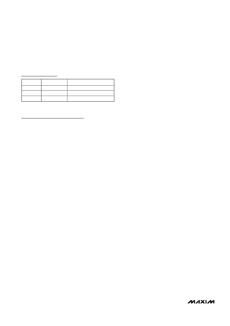
Component Suppliers
SUPPLIER
Johnson
M/A-COM
Murata
PHONE
507-833-8822
800-366-2266
770-436-1300
WEBSITE
www.johnsoncomponents.com
www.macom.com
www.murata.com
Note:
Indicate that you are using the MAX2023 when contacting
these component suppliers.
相关PDF资料 |
PDF描述 |
|---|---|
| MAX2023EVKIT | Evaluation Kit |
| MAX2029 | High-Linearity, 815MHz to 1000MHz Upconversion/ Downconversion Mixer with LO Buffer/Switch |
| MAX2031_1 | Evaluation Kit |
| MAX2031EVKIT | Evaluation Kit |
| MAX2031 | High-Linearity, 815MHz to 1000MHz Upconversion/ Downconversion Mixer with LO Buffer/Switch |
相关代理商/技术参数 |
参数描述 |
|---|---|
| MAX2023ETX | 功能描述:调节器/解调器 1.5GHz-2.3GHz Quad Mod/Demod RoHS:否 制造商:Texas Instruments 封装 / 箱体:PVQFN-N24 封装:Reel |
| MAX2023ETX+ | 功能描述:调节器/解调器 1.5GHz-2.3GHz Quad Mod/Demod RoHS:否 制造商:Texas Instruments 封装 / 箱体:PVQFN-N24 封装:Reel |
| MAX2023ETX+T | 功能描述:调节器/解调器 1.5GHz-2.3GHz Quad Mod/Demod RoHS:否 制造商:Texas Instruments 封装 / 箱体:PVQFN-N24 封装:Reel |
| MAX2023ETX-T | 功能描述:调节器/解调器 1.5GHz-2.3GHz Quad Mod/Demod RoHS:否 制造商:Texas Instruments 封装 / 箱体:PVQFN-N24 封装:Reel |
| MAX2023EVKIT | 功能描述:调节器/解调器 Hi-Dynamic-Range Direct Upconversion 1500MHz - 2300MHz Quadrature Mod/Dem RoHS:否 制造商:Texas Instruments 封装 / 箱体:PVQFN-N24 封装:Reel |
发布紧急采购,3分钟左右您将得到回复。