- 您现在的位置:买卖IC网 > PDF目录18755 > MAX2265EUE+T (Maxim Integrated)IC AMP POWER CELL 16TSSOP-EP PDF资料下载
参数资料
| 型号: | MAX2265EUE+T |
| 厂商: | Maxim Integrated |
| 文件页数: | 13/15页 |
| 文件大小: | 0K |
| 描述: | IC AMP POWER CELL 16TSSOP-EP |
| 产品培训模块: | Lead (SnPb) Finish for COTS Obsolescence Mitigation Program |
| 标准包装: | 2,500 |
| 频率: | 824MHz ~ 849MHz |
| 增益: | 21dB |
| RF 型: | CDMA |
| 电源电压: | 2.7 V ~ 5.5 V |
| 电流 - 电源: | 90mA |
| 封装/外壳: | 16-TSSOP(0.173",4.40mm)裸露焊盘 |
| 包装: | 带卷 (TR) |
�� �
�
�2.7V,� Single-Supply,� Cellular-Band�
�Linear� Power� Amplifiers�
�each� device;� suggested� component� values,� suppliers,�
�and� part� numbers� are� listed� in� Table� 1.� These� values�
�are� optimized� for� best� simultaneous� efficiency� and�
�return� loss� performance.� Use� high-quality� components�
�in� these� matching� circuits� for� greatest� efficiency.�
�Layout� and� Power-Supply� Bypassing�
�A� properly� designed� PC� board� is� essential� to� any�
�RF/microwave� circuit.� Be� sure� to� use� controlled� imped-�
�ance� lines� on� all� high-frequency� inputs� and� outputs.�
�Proper� grounding� of� the� GND� pins� is� fundamental;� if� the�
�PC� board� uses� a� topside� RF� ground,� connect� all� GND�
�pins� (especially� the� TSSOP� package� exposed� GND� pad)�
�directly� to� it.� On� boards� where� the� ground� plane� is� not� on�
�the� component� side,� it’s� best� to� connect� all� GND� pins� to�
�To� minimize� coupling� between� different� sections� of� the�
�system,� the� ideal� power-supply� layout� is� a� star� configu-�
�ration� with� a� large� decoupling� capacitor� at� a� central�
�V� CC� node.� The� V� CC� traces� branch� out� from� this� central�
�node,� each� leading� to� a� separate� V� CC� node� on� the� PC�
�board.� A� second� bypass� capacitor� with� low� ESR� at� the�
�RF� frequency� of� operation� is� located� at� the� end� of� each�
�trace.� This� arrangement� provides� local� decoupling� at�
�the� V� CC� pin.�
�Input� and� output� impedance-matching� networks� are�
�very� sensitive� to� layout-related� parasitics.� It� is� important�
�to� keep� all� matching� components� as� close� to� the� IC� as�
�possible� to� minimize� the� effects� of� stray� inductance�
�and� stray� capacitance� of� PC� board� traces.�
�the� ground� plane� with� plated� through-holes� close� to� the�
�package.�
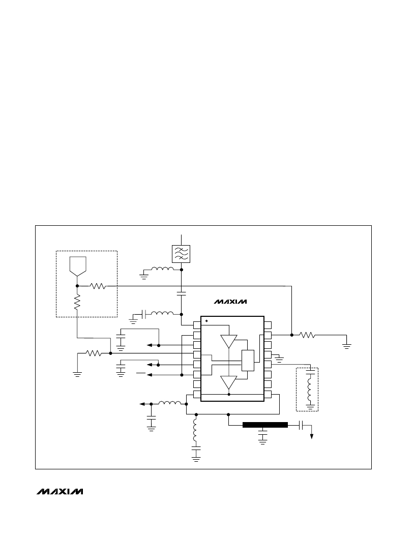
�RFIN�
�OPTIONAL� TB� CIRCUIT�
�TX�
�POWER�
�L1�
�R� TB2�
�C1�
�R� TB1�
�MAX2265�
�R1�
�C3�
�C11�
�V� CC�
�C12� V� CC�
�SHDN�
�L3�
�1�
�2�
�3�
�4�
�5�
�6�
�16�
�15�
�14�
�13�
�12�
�11�
�R2�
�C13�
�7�
�10�
�V� CC�
�C4�
�L4�
�8�
�L6�
�9�
�C7�
�C9�
�L7� OPTIONAL�
�NOISE-REDUCTION�
�CIRCUIT�
�RFOUT�
�C6�
�Figure� 2.� MAX2265� Typical� Application� Circuit�
�______________________________________________________________________________________�
�13�
�相关PDF资料 |
PDF描述 |
|---|---|
| JN5139-Z01-M/01R1V | MODULE ZIGBEE SMA CONN JN5139 |
| MAX2242EBC+T | IC PWR AMP 2.4GHZ-2.5GHZ UCSP |
| DOC050F-020.0M | OSC OCXO 20.0 MHZ 3.3V SMT |
| ST-7-56 | XFRMR PWR 115V 28V 1.3A 36VA |
| A-20GV21-B | BASIC SWITCH |
相关代理商/技术参数 |
参数描述 |
|---|---|
| MAX2265EVKIT | 功能描述:放大器 IC 开发工具 MAX2264/5/6 Eval Kit RoHS:否 制造商:International Rectifier 产品:Demonstration Boards 类型:Power Amplifiers 工具用于评估:IR4302 工作电源电压:13 V to 23 V |
| MAX2266 | 制造商:MAXIM 制造商全称:Maxim Integrated Products 功能描述:Evaluation Kit for the MAX2406[MAX2406EVKIT ] |
| MAX2266EUE | 功能描述:射频放大器 RoHS:否 制造商:Skyworks Solutions, Inc. 类型:Low Noise Amplifier 工作频率:2.3 GHz to 2.8 GHz P1dB:18.5 dBm 输出截获点:37.5 dBm 功率增益类型:32 dB 噪声系数:0.85 dB 工作电源电压:5 V 电源电流:125 mA 测试频率:2.6 GHz 最大工作温度:+ 85 C 安装风格:SMD/SMT 封装 / 箱体:QFN-16 封装:Reel |
| MAX2266EUE+T | 功能描述:射频放大器 RoHS:否 制造商:Skyworks Solutions, Inc. 类型:Low Noise Amplifier 工作频率:2.3 GHz to 2.8 GHz P1dB:18.5 dBm 输出截获点:37.5 dBm 功率增益类型:32 dB 噪声系数:0.85 dB 工作电源电压:5 V 电源电流:125 mA 测试频率:2.6 GHz 最大工作温度:+ 85 C 安装风格:SMD/SMT 封装 / 箱体:QFN-16 封装:Reel |
| MAX2266EUE-T | 功能描述:射频放大器 RoHS:否 制造商:Skyworks Solutions, Inc. 类型:Low Noise Amplifier 工作频率:2.3 GHz to 2.8 GHz P1dB:18.5 dBm 输出截获点:37.5 dBm 功率增益类型:32 dB 噪声系数:0.85 dB 工作电源电压:5 V 电源电流:125 mA 测试频率:2.6 GHz 最大工作温度:+ 85 C 安装风格:SMD/SMT 封装 / 箱体:QFN-16 封装:Reel |
发布紧急采购,3分钟左右您将得到回复。