- 您现在的位置:买卖IC网 > PDF目录10618 > MAX232AEWE+ (Maxim Integrated Products)IC 2DVR/2RCVR RS232 5V 16-SOIC PDF资料下载
参数资料
| 型号: | MAX232AEWE+ |
| 厂商: | Maxim Integrated Products |
| 文件页数: | 6/38页 |
| 文件大小: | 0K |
| 描述: | IC 2DVR/2RCVR RS232 5V 16-SOIC |
| 产品培训模块: | Lead (SnPb) Finish for COTS Obsolescence Mitigation Program |
| 标准包装: | 46 |
| 类型: | 收发器 |
| 驱动器/接收器数: | 2/2 |
| 规程: | RS232 |
| 电源电压: | 4.5 V ~ 5.5 V |
| 安装类型: | 表面贴装 |
| 封装/外壳: | 16-SOIC(0.295",7.50mm 宽) |
| 供应商设备封装: | 16-SOIC W |
| 包装: | 管件 |
| 产品目录页面: | 1401 (CN2011-ZH PDF) |
第1页第2页第3页第4页第5页当前第6页第7页第8页第9页第10页第11页第12页第13页第14页第15页第16页第17页第18页第19页第20页第21页第22页第23页第24页第25页第26页第27页第28页第29页第30页第31页第32页第33页第34页第35页第36页第37页第38页
_______________Detailed Description
The MAX220–MAX249 contain four sections: dual
charge-pump DC-DC voltage converters, RS-232 dri-
vers, RS-232 receivers, and receiver and transmitter
enable control inputs.
Dual Charge-Pump Voltage Converter
The MAX220–MAX249 have two internal charge-pumps
that convert +5V to ±10V (unloaded) for RS-232 driver
operation. The first converter uses capacitor C1 to dou-
ble the +5V input to +10V on C3 at the V+ output. The
second converter uses capacitor C2 to invert +10V to
-10V on C4 at the V- output.
A small amount of power may be drawn from the +10V
(V+) and -10V (V-) outputs to power external circuitry
(see the
Typical Operating Characteristics section),
except on the MAX225 and MAX245–MAX247, where
these pins are not available. V+ and V- are not regulated,
so the output voltage drops with increasing load current.
Do not load V+ and V- to a point that violates the mini-
mum ±5V EIA/TIA-232E driver output voltage when
sourcing current from V+ and V- to external circuitry.
When using the shutdown feature in the MAX222,
MAX225, MAX230, MAX235, MAX236, MAX240,
MAX241, and MAX245–MAX249, avoid using V+ and V-
to power external circuitry. When these parts are shut
down, V- falls to 0V, and V+ falls to +5V. For applica-
tions where a +10V external supply is applied to the V+
pin (instead of using the internal charge pump to gen-
erate +10V), the C1 capacitor must not be installed and
the SHDN pin must be connected to VCC. This is
because V+ is internally connected to VCC in shutdown
mode.
RS-232 Drivers
The typical driver output voltage swing is ±8V when
loaded with a nominal 5k
Ω RS-232 receiver and VCC =
+5V. Output swing is guaranteed to meet the EIA/TIA-
232E and V.28 specification, which calls for ±5V mini-
mum driver output levels under worst-case conditions.
These include a minimum 3k
Ω load, VCC = +4.5V, and
maximum operating temperature. Unloaded driver out-
put voltage ranges from (V+ -1.3V) to (V- +0.5V).
Input thresholds are both TTL and CMOS compatible.
The inputs of unused drivers can be left unconnected
since 400k
Ω input pullup resistors to VCC are built in
(except for the MAX220). The pullup resistors force the
outputs of unused drivers low because all drivers invert.
The internal input pullup resistors typically source 12A,
except in shutdown mode where the pullups are dis-
abled. Driver outputs turn off and enter a high-imped-
ance state—where leakage current is typically
microamperes (maximum 25A)—when in shutdown
mode, in three-state mode, or when device power is
removed. Outputs can be driven to ±15V. The power-
supply current typically drops to 8A in shutdown mode.
The MAX220 does not have pullup resistors to force the
outputs of the unused drivers low. Connect unused
inputs to GND or VCC.
The MAX239 has a receiver three-state control line, and
the MAX223, MAX225, MAX235, MAX236, MAX240,
and MAX241 have both a receiver three-state control
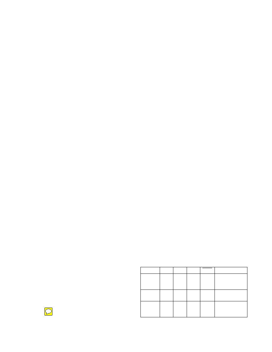
line and a low-power shutdown control. Table 2 shows
the effects of the shutdown control and receiver three-
state control on the receiver outputs.
The receiver TTL/CMOS outputs are in a high-imped-
ance, three-state mode whenever the three-state enable
line is high (for the MAX225/MAX235/MAX236/MAX239–
MAX241), and are also high-impedance whenever the
shutdown control line is high.
When in low-power shutdown mode, the driver outputs
are turned off and their leakage current is less than 1A
with the driver output pulled to ground. The driver output
leakage remains less than 1A, even if the transmitter
output is backdriven between 0V and (VCC + 6V). Below
-0.5V, the transmitter is diode clamped to ground with
1k
Ω series impedance. The transmitter is also zener
clamped to approximately VCC + 6V, with a series
impedance of 1k
Ω.
The driver output slew rate is limited to less than 30V/s
as required by the EIA/TIA-232E and V.28 specifica-
tions. Typical slew rates are 24V/s unloaded and
10V/s loaded with 3
Ω and 2500pF.
RS-232 Receivers
EIA/TIA-232E and V.28 specifications define a voltage
level greater than 3V as a logic 0, so all receivers invert.
Input thresholds are set at 0.8V and 2.4V, so receivers
respond to TTL level inputs as well as EIA/TIA-232E and
V.28 levels.
The receiver inputs withstand an input overvoltage up
to ±25V and provide input terminating resistors with
+5V-Powered, Multichannel RS-232
Drivers/Receivers
PART
SHDN
EN
EN(R)
RECEIVERS
MAX223
__
Low
High
X
Low
High
High Impedance
Active
High Impedance
MAX225
__
High Impedance
Active
__
MAX235
MAX236
MAX240
Low
High
__
Low
High
X
High Impedance
Active
High Impedance
Table 2. Three-State Control of Receivers
Low
High
SHDN
__
14
Maxim Integrated
MAX220–MAX249
相关PDF资料 |
PDF描述 |
|---|---|
| MAX3815ACCM+ | IC DGTL VIDEO EQUALIZER 48TQFP |
| MAX3816ACUE+ | IC I2C 2WIRE EXTENDER 16-TSSOP |
| AD8324JRQZ-REEL7 | IC LINE DRIVER CBL 3.3V 20QSOP |
| VE-JWB-MW-F2 | CONVERTER MOD DC/DC 95V 100W |
| MAX7450ESA+ | IC CONDITIONER VIDEO 8-SOIC |
相关代理商/技术参数 |
参数描述 |
|---|---|
| MAX232AEWE+ | 功能描述:RS-232接口集成电路 5V MultiCh RS-232 Driver/Receiver RoHS:否 制造商:Exar 数据速率:52 Mbps 工作电源电压:5 V 电源电流:300 mA 工作温度范围:- 40 C to + 85 C 安装风格:SMD/SMT 封装 / 箱体:LQFP-100 封装: |
| MAX232AEWE+G068 | 功能描述:RS-232接口集成电路 5V RS-232 Device RoHS:否 制造商:Exar 数据速率:52 Mbps 工作电源电压:5 V 电源电流:300 mA 工作温度范围:- 40 C to + 85 C 安装风格:SMD/SMT 封装 / 箱体:LQFP-100 封装: |
| MAX232AEWE+T | 功能描述:RS-232接口集成电路 5V MultiCh RS-232 Driver/Receiver RoHS:否 制造商:Exar 数据速率:52 Mbps 工作电源电压:5 V 电源电流:300 mA 工作温度范围:- 40 C to + 85 C 安装风格:SMD/SMT 封装 / 箱体:LQFP-100 封装: |
| MAX232AEWE+TG068 | 功能描述:RS-232接口集成电路 5V RS-232 Device RoHS:否 制造商:Exar 数据速率:52 Mbps 工作电源电压:5 V 电源电流:300 mA 工作温度范围:- 40 C to + 85 C 安装风格:SMD/SMT 封装 / 箱体:LQFP-100 封装: |
| MAX232AEWE-T | 功能描述:RS-232接口集成电路 RoHS:否 制造商:Exar 数据速率:52 Mbps 工作电源电压:5 V 电源电流:300 mA 工作温度范围:- 40 C to + 85 C 安装风格:SMD/SMT 封装 / 箱体:LQFP-100 封装: |
发布紧急采购,3分钟左右您将得到回复。