- 您现在的位置:买卖IC网 > PDF目录383346 > MAX2410 (Maxim Integrated Products, Inc.) Low-Cost RF Up/Downconverter with LNA and PA Driver PDF资料下载
参数资料
| 型号: | MAX2410 |
| 厂商: | Maxim Integrated Products, Inc. |
| 英文描述: | Low-Cost RF Up/Downconverter with LNA and PA Driver |
| 中文描述: | 低成本、RF上/下变频器,带有LNA及PA驱动器 |
| 文件页数: | 8/12页 |
| 文件大小: | 179K |
| 代理商: | MAX2410 |
M
Low-Cost RF Up/Downc onverter
with LNA and PA Driver
8
_______________________________________________________________________________________
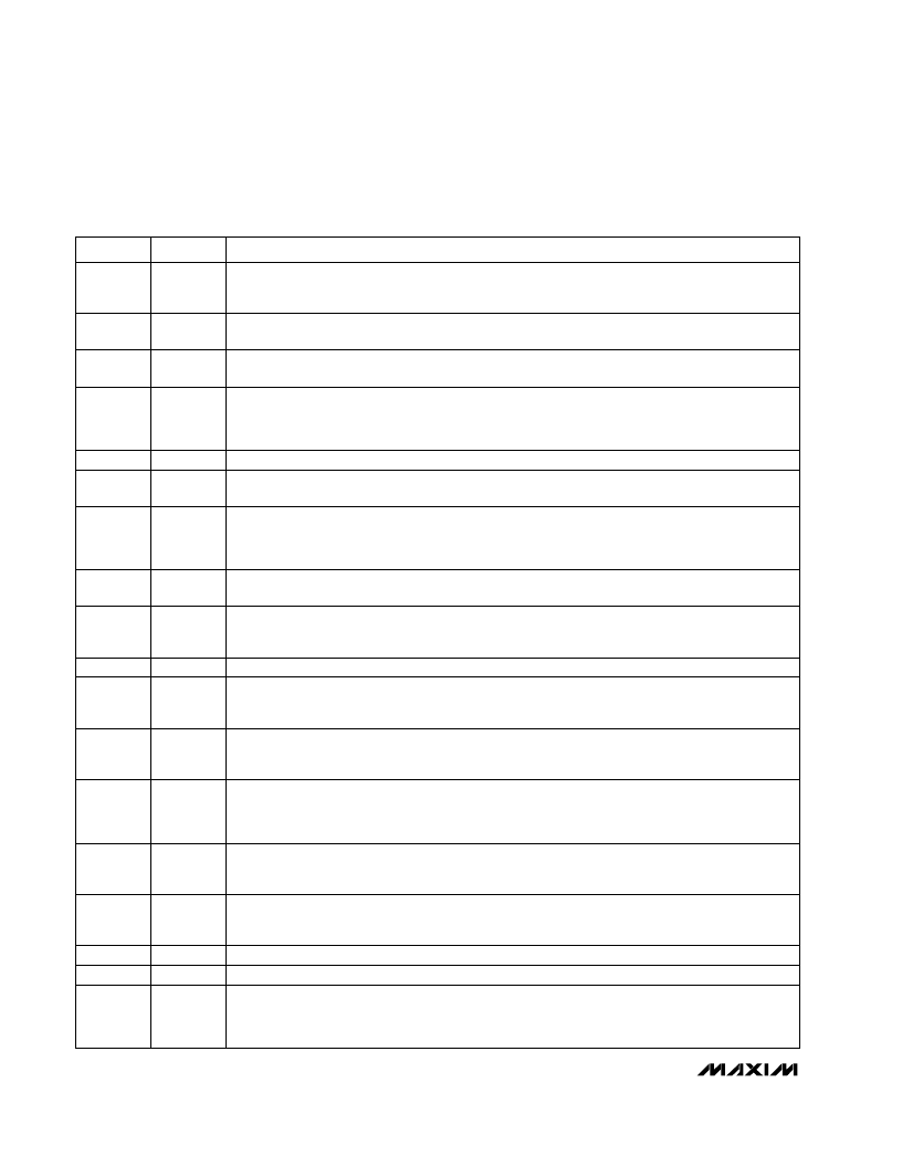
______________________________________________________________Pin Desc ription
LNA Output. AC couple to this pin. This output typically provides a VSWR of better than 2:1 at frequen-
cies from 1.7GHz to 3GHz with no external matching components. At other frequencies, a matching
network may be required to match this pin to an external filter. Consult the Typical Operating
Characteristics for a plot of LNA Output Impedance vs. Frequency.
LNAOUT
27
LNA Output Ground. Connect to PC board ground plane with minimal inductance.
GND
26
Receive Mixer Input Ground. Connect to PC board ground plane with minimal inductance.
GND
25
RF Input to Receive Mixer (Downconverter). AC couple to this pin. This input typically requires a matching
network for connecting to an external filter. See the Typical Operating Characteristicsfor a plot of RXMXIN
Impedance vs. Frequency.
RXMXIN
24
IF Input of Transmit Mixer (Upconverter). AC couple to this pin. IFIN presents a high input impedance
and typically requires a matching network. See the Typical Operating Characteristics for a plot of IFIN
Impedance vs. Frequency.
IFIN
22
IF Output of Receive Mixer (Downconverter). AC couple to this pin. This output is an open collector and
should be pulled up to V
CC
with an inductor. This inductor can be part of the matching network to the
desired IF impedance. Alternatively, a resistor can be placed in parallel to this inductor to set a termi-
nating impedance. See the Typical Operating Circuitfor more information.
IFOUT
21
RF Output of Transmit Mixer (Upconverter). AC couple to this pin. Use an external shunt inductor to
V
CC
as part of a matching network to 50
. This also provides DC bias. See the Typical Operating
Characteristics for a plot of TXMXOUT Impedance vs. Frequency.
TXMXOUT
19
RF Input to Variable-Gain Power-Amplifier Driver. AC couple to this pin. Internally matched to 50
. This
input typically provides a 2:1 VSWR at 1.9GHz. See the Typical Operating Characteristics for a plot of
PADRIN Impedance vs. Frequency.
PADRIN
16
Power-Amplifier Driver Input Ground. Connect to PC board ground plane with minimal inductance.
GND
15, 17
Power-Amplifier Driver Output. AC couple to this pin. Use external shunt inductor to V
CC
to match this pin
to 50
. This also provides DC bias. See the Typical Operating Characteristics for a plot of PADROUT
Impedance vs. Frequency.
PADROUT
13
Gain-Control Input for Power-Amplifier Driver. By applying an analog control voltage between 0V and
2.15V, the gain of the PA driver can be adjusted over a 35dB range. Connect to V
CC
for maximum gain.
GC
11
Logic-Level Enable for Transmitter Circuitry. A logic high turns on the transmitter. When TXEN and
RXEN are both at a logic high, the part is placed in standby mode, with 160μA (typical) supply current.
If TXEN and RXEN are both at a logic low, the part is set to shutdown mode, with 0.1μA (typical) supply
current.
TXEN
9
50
Inverting Local-Oscillator Input Port. For single-ended operation connect
LO
directly to GND. If a
differential LO signal is available, AC couple the inverted LO signal to this pin.
LO
8
50
Local-Oscillator (LO) Input Port. AC couple to this pin.
LO
7
Logic-Level Enable for Receiver Circuitry. A logic high turns on the receiver. When TXEN and RXEN are
both at a logic high, the part is placed in standby mode, with a supply current of 160μA (typical). If
TXEN and RXEN are both at a logic low, the part is set to shutdown mode, with a supply current of
0.1μA (typical).
RXEN
6
Supply Voltage (2.7V to 5.5V). Bypass V
CC
to GND at each pin with a 47pF capacitor as close to each
pin as possible.
V
CC
5, 10
RF Input to the LNA. AC couple to this pin. At 1.9GHz, LNAIN can be easily matched to 50
with one
external shunt 1pF capacitor.
LNAIN
2
PIN
Ground. Connect to PC board ground plane with minimal inductance.
GND
1, 3, 4, 12,
14, 18, 20,
23, 28
FUNCTION
NAME
相关PDF资料 |
PDF描述 |
|---|---|
| MAX2411AEEI | Low-Cost RF Up/Downconverter with LNA and PA Driver |
| MAX2411 | Low-Cost RF Up/Downconverter with LNA and PA Driver |
| MAX2411A | Hex Buffers/Drivers With Open-Collector High-Voltage Outputs 14-SOIC 0 to 70 |
| MAX2424 | 900MHz Image-Reject Receivers with Transmit Mixer |
| MAX2424EAI | Dual monostable multivibrators with Schmitt-trigger inputs 16-PDIP 0 to 70 |
相关代理商/技术参数 |
参数描述 |
|---|---|
| MAX2410EEI | 功能描述:上下转换器 RoHS:否 制造商:Texas Instruments 产品:Down Converters 射频:52 MHz to 78 MHz 中频:300 MHz LO频率: 功率增益: P1dB: 工作电源电压:1.8 V, 3.3 V 工作电源电流:120 mA 最大功率耗散:1 W 最大工作温度:+ 85 C 安装风格:SMD/SMT 封装 / 箱体:PQFP-128 |
| MAX2410EEI+ | 功能描述:上下转换器 RF Up/Down Cnvrtr w/LNA & PA Driver RoHS:否 制造商:Texas Instruments 产品:Down Converters 射频:52 MHz to 78 MHz 中频:300 MHz LO频率: 功率增益: P1dB: 工作电源电压:1.8 V, 3.3 V 工作电源电流:120 mA 最大功率耗散:1 W 最大工作温度:+ 85 C 安装风格:SMD/SMT 封装 / 箱体:PQFP-128 |
| MAX2410EEI+T | 功能描述:上下转换器 RF Up/Down Cnvrtr w/LNA & PA Driver RoHS:否 制造商:Texas Instruments 产品:Down Converters 射频:52 MHz to 78 MHz 中频:300 MHz LO频率: 功率增益: P1dB: 工作电源电压:1.8 V, 3.3 V 工作电源电流:120 mA 最大功率耗散:1 W 最大工作温度:+ 85 C 安装风格:SMD/SMT 封装 / 箱体:PQFP-128 |
| MAX2410EEI-T | 功能描述:上下转换器 RoHS:否 制造商:Texas Instruments 产品:Down Converters 射频:52 MHz to 78 MHz 中频:300 MHz LO频率: 功率增益: P1dB: 工作电源电压:1.8 V, 3.3 V 工作电源电流:120 mA 最大功率耗散:1 W 最大工作温度:+ 85 C 安装风格:SMD/SMT 封装 / 箱体:PQFP-128 |
| MAX2410EVKIT | 功能描述:射频开发工具 MAX2410 Eval Kit RoHS:否 制造商:Taiyo Yuden 产品:Wireless Modules 类型:Wireless Audio 工具用于评估:WYSAAVDX7 频率: 工作电源电压:3.4 V to 5.5 V |
发布紧急采购,3分钟左右您将得到回复。