- 您现在的位置:买卖IC网 > Datasheet目录472 > MAX2410EVKIT (Maxim Integrated)EVAL KIT MAX2410 Datasheet资料下载
参数资料
| 型号: | MAX2410EVKIT |
| 厂商: | Maxim Integrated |
| 文件页数: | 11/12页 |
| 文件大小: | 0K |
| 描述: | EVAL KIT MAX2410 |
| 标准包装: | 1 |
| 系列: | * |
�� �
�
�Low-Cost� RF� Up/Downconverter�
�with� LNA� and� PA� Driver�
�Standby� Mode�
�When� the� TXEN� and� RXEN� pins� are� both� set� to� logic� 1,�
�all� functions� are� disabled� and� the� supply� current� drops�
�to� 160μA� (typical).� This� mode� is� called� standby,� and� it�
�corresponds� to� a� standby� mode� on� the� compatible� IF�
�transceiver� chips� MAX2510� and� MAX2511.�
�Applications� Information�
�Extended� Frequency� Range�
�The� MAX2410� has� been� characterized� at� 1.9GHz� for� use�
�in� PCS-band� applications;� however,� it� operates� over� a�
�much� wider� frequency� range.� The� LNA� gain� and� noise�
�figure,� as� well� as� mixer� conversion� gain,� are� plotted� over�
�a� wide� frequency� range� in� the� Typical� Operating�
�Characteristics.� When� operating� the� device� at� RF� fre-�
�quencies� other� than� those� specified� in� the� AC� Electrical�
�Characteristics� table,� it� may� be� necessary� to� design� or�
�alter� the� matching� networks� on� the� RF� ports.� If� the� IF�
�frequency� is� different� than� that� specified� in� the� AC�
�Electrical� Characteristics� table,� the� IFIN� and� IFOUT�
�matching� networks� must� be� altered.� The� Typical�
�vs.� Frequency� on� all� RF� and� IF� pins� for� use� in� designing�
�matching� networks.� The� LO� port� (LO� and� LO� )� is� internally�
�terminated� with� 50� ?� resistors� and� provides� a� VSWR� of�
�approximately� 1.2:1� to� 2GHz� and� 2:1� up� to� 3GHz.�
�Layout� Issues�
�A� properly� designed� PC� board� is� an� essential� part� of�
�any� RF/microwave� circuit.� Be� sure� to� use� controlled�
�impedance� lines� on� all� high-frequency� inputs� and� out-�
�puts.� Use� low-inductance� connections� to� ground� on� all�
�GND� pins,� and� place� decoupling� capacitors� close� to� all�
�V� CC� connections.�
�For� the� power� supplies,� a� star� topology� works� well.� In� a�
�star� topology,� each� V� CC� node� in� the� circuit� has� its� own�
�path� to� the� central� V� CC� ,� and� its� own� decoupling� capaci-�
�tor� which� provides� a� low� impedance� at� the� RF� frequen-�
�cy� of� interest.� The� central� V� CC� node� has� a� large�
�decoupling� capacitor� as� well,� to� provide� good� isolation�
�between� the� different� sections� of� the� MAX2410.� The�
�MAX2410� EV� kit� layout� can� be� used� as� a� guide� to� inte-�
�grating� the� MAX2410� into� your� design.�
�Operating� Characteristics� provide� Port� Impedance� Data�
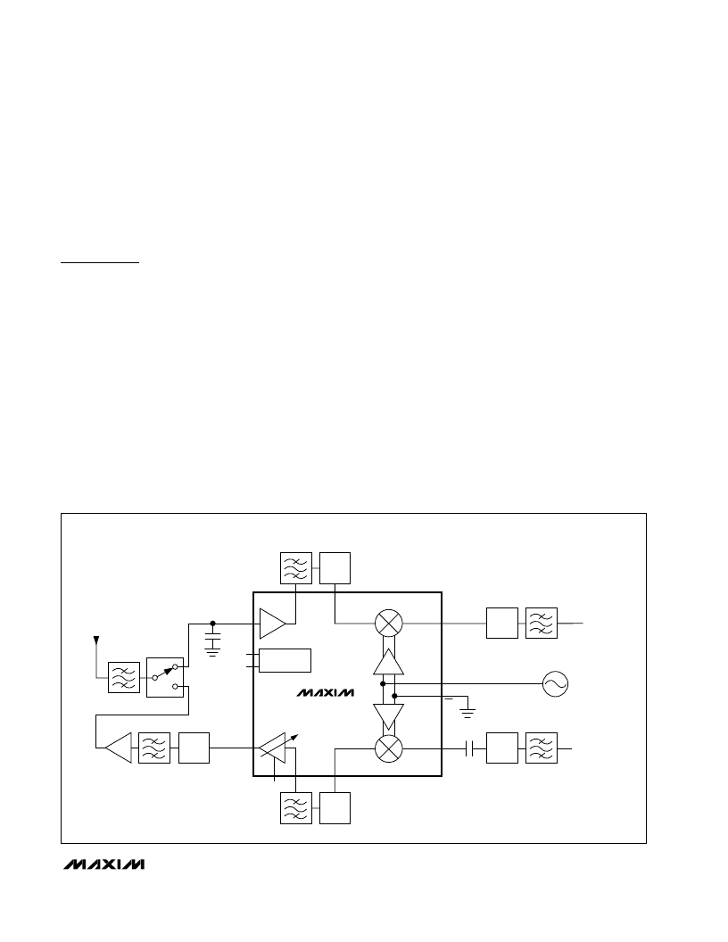
�_________________________________________Typical� Application� Block� Diagram�
�RF�
�BPF�
�MATCH�
�RX� MIXER�
�ANTENNA�
�RF�
�BPF�
�T/R�
�LNAIN�
�RXEN�
�LNA�
�POWER�
�IFOUT�
�MATCH�
�IF�
�BPF�
�RECEIVE�
�IFOUT�
�TXEN�
�MANAGEMENT�
�LO�
�LOCAL�
�OSCILLATOR�
�PA� DRIVER�
�MAX2410�
�LO�
�RF�
�BPF�
�MATCH�
�PADROUT�
�GC�
�TX� MIXER�
�IFIN�
�CBLOCK�
�MATCH�
�IF�
�BPF�
�TRANSMIT�
�IFIN�
�RF�
�BPF�
�MATCH�
�______________________________________________________________________________________�
�11�
�相关PDF资料 |
PDF描述 |
|---|---|
| MAX2411AEEI+ | IC UP/DOWNCONVERTER 28-QSOP |
| MAX2510EVKIT-SO | EVAL KIT MAX2510 |
| MAX2511EVKIT | EVAL KIT MAX2511 |
| MAX2538ETI+T | IC LNA/MIXER CELL/PCS/GPS 28TQFN |
| MAX2608EVKIT | EVAL KIT |
相关代理商/技术参数 |
参数描述 |
|---|---|
| MAX2411AE/D | 功能描述:上下转换器 Low-Cost RF Up/Downconverter with LNA and PA Driver RoHS:否 制造商:Texas Instruments 产品:Down Converters 射频:52 MHz to 78 MHz 中频:300 MHz LO频率: 功率增益: P1dB: 工作电源电压:1.8 V, 3.3 V 工作电源电流:120 mA 最大功率耗散:1 W 最大工作温度:+ 85 C 安装风格:SMD/SMT 封装 / 箱体:PQFP-128 |
| MAX2411AEEI | 功能描述:上下转换器 RF Up/Down Cnvrtr w/LNA & PA Driver RoHS:否 制造商:Texas Instruments 产品:Down Converters 射频:52 MHz to 78 MHz 中频:300 MHz LO频率: 功率增益: P1dB: 工作电源电压:1.8 V, 3.3 V 工作电源电流:120 mA 最大功率耗散:1 W 最大工作温度:+ 85 C 安装风格:SMD/SMT 封装 / 箱体:PQFP-128 |
| MAX2411AEEI+ | 功能描述:上下转换器 RF Up/Down Cnvrtr w/LNA & PA Driver RoHS:否 制造商:Texas Instruments 产品:Down Converters 射频:52 MHz to 78 MHz 中频:300 MHz LO频率: 功率增益: P1dB: 工作电源电压:1.8 V, 3.3 V 工作电源电流:120 mA 最大功率耗散:1 W 最大工作温度:+ 85 C 安装风格:SMD/SMT 封装 / 箱体:PQFP-128 |
| MAX2411AEEI+T | 功能描述:上下转换器 RF Up/Down Cnvrtr w/LNA & PA Driver RoHS:否 制造商:Texas Instruments 产品:Down Converters 射频:52 MHz to 78 MHz 中频:300 MHz LO频率: 功率增益: P1dB: 工作电源电压:1.8 V, 3.3 V 工作电源电流:120 mA 最大功率耗散:1 W 最大工作温度:+ 85 C 安装风格:SMD/SMT 封装 / 箱体:PQFP-128 |
| MAX2411AEEI-T | 功能描述:上下转换器 RF Up/Down Cnvrtr w/LNA & PA Driver RoHS:否 制造商:Texas Instruments 产品:Down Converters 射频:52 MHz to 78 MHz 中频:300 MHz LO频率: 功率增益: P1dB: 工作电源电压:1.8 V, 3.3 V 工作电源电流:120 mA 最大功率耗散:1 W 最大工作温度:+ 85 C 安装风格:SMD/SMT 封装 / 箱体:PQFP-128 |
发布紧急采购,3分钟左右您将得到回复。