- 您现在的位置:买卖IC网 > PDF目录18736 > MAX2510EEI+ (Maxim Integrated)IC TXRX IF W/RSSI&MODLTR 28-QSOP PDF资料下载
参数资料
| 型号: | MAX2510EEI+ |
| 厂商: | Maxim Integrated |
| 文件页数: | 11/12页 |
| 文件大小: | 0K |
| 描述: | IC TXRX IF W/RSSI&MODLTR 28-QSOP |
| 产品培训模块: | Lead (SnPb) Finish for COTS Obsolescence Mitigation Program |
| 标准包装: | 50 |
| 频率: | 100MHz ~ 600MHz |
| 应用: | ISM |
| 功率 - 输出: | 1dBm |
| 电源电压: | 2.7 V ~ 5.5 V |
| 电流 - 接收: | 20mA |
| 电流 - 传输: | 25mA |
| 数据接口: | PCB,表面贴装 |
| 天线连接器: | PCB,表面贴装 |
| 工作温度: | -40°C ~ 85°C |
| 封装/外壳: | 28-QSOP |
| 包装: | 管件 |
�� �
�
�Low-Voltage� IF� Transceiver� with�
�Limiter/RSSI� and� Quadrature� Modulator�
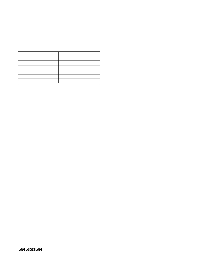
�Table� 2.� RXIN� or� RXIN� Input� Impedance�
�FREQUENCY� SERIES� IMPEDANCE�
�(MHz)� (� ?� )�
�noise� amplifier� (LNA)� that� can� operate� over� the� same�
�supply� voltage� range.� The� MAX2630–MAX2633� family�
�of� amplifiers� meets� this� requirement.� In� many� applica-�
�tions,� the� MAX2510’s� transmit� output� power� is� sufficient�
�100�
�200�
�300�
�400�
�500�
�275� -� j203�
�149� -� j184�
�94� -� j143�
�64� -� j109�
�53� -� j87�
�to� eliminate� the� need� for� an� external� power� amplifier.�
�______________________Layout� Issues�
�A� well-designed� PC� board� is� an� essential� part� of� an� RF�
�circuit.� Use� the� MAX2510� evaluation� kit� and� the� recom-�
�mendations� below� as� guides� to� generate� your� own�
�layout.�
�Receive� IF� Filter�
�The� interstage� filter,� located� between� the� MIXOUT� pin�
�and� the� LIMIN� pin,� is� typically� a� three-terminal,� 330� ?� ,�
�10.7MHz� bandpass� filter.� This� filter� prevents� the� limiter�
�from� acting� on� any� undesired� signals� that� are� present�
�at� the� mixer’s� output,� such� as� LO� feedthrough,� out-of-�
�band� channel� leakage,� and� spurious� mixer� products.�
�The� filter� connections� are� also� set� up� to� feed� DC� bias�
�from� VREF� into� LIMIN� and� MIXOUT� through� two� 330� ?�
�filter-termination� resistors.� (See� the� Typical� Operating�
�Circuit� for� more� information).�
�Transmit� Output� Matching�
�The� transmit� outputs,� TXOUT� and� TXOUT� ,� are� open-�
�collector� outputs� and� therefore� present� a� high�
�impedance.�
�For� differential� drive,� TXOUT� and� TXOUT� are� connected�
�to� V� CC� via� chokes,� and� each� side� is� AC� coupled� to� the�
�load.� A� terminating� resistor� between� TXOUT� and�
�TXOUT� sets� the� output� impedance.� This� resistor� pro-�
�vides� a� stable� means� of� matching� to� the� load.�
�TXOUT� and� TXOUT� are� voltage-swing� limited,� and�
�therefore� cannot� drive� the� specified� maximum� power�
�across� more� than� 150� ?� load� impedance.� This� load�
�impedance� typically� consists� of� a� shunt-terminating�
�resistor� in� parallel� with� a� filter� load� impedance.� To� drive�
�higher� output� load� impedances,� the� gain� must� be�
�reduced� (via� the� GC� pin)� to� avoid� saturating� the� TX� out-�
�put� stage.�
�For� single-ended� applications,� connect� the� unused� TX�
�output� output� pin� directly� to� V� CC� .�
�400MHz� ISM� Applications�
�The� MAX2510� can� be� used� as� a� front-end� IC� in� appli-�
�cations� where� the� RF� carrier� frequency� is� in� the�
�400MHz� ISM� band.� In� this� case,� Maxim� recommends�
�preceding� the� MAX2510� receiver� section� with� a� low-�
�Power-Supply� Layout�
�A� star� topology,� which� has� a� heavily� decoupled� central�
�V� CC� node,� is� the� ideal� power-supply� layout� for� minimiz-�
�ing� coupling� between� different� sections� of� the� chip.� The�
�V� CC� traces� branch� out� from� this� node,� each� going� to�
�one� V� CC� connection� in� the� MAX2510� typical� operating�
�circuit.� At� the� end� of� each� of� these� traces� is� a� bypass�
�capacitor� that� presents� low� impedance� at� the� RF� fre-�
�quency� of� interest.� This� method� provides� local� decou-�
�pling� at� each� V� CC� pin.� At� high� frequencies,� any� signal�
�leaking� out� of� a� supply� pin� sees� a� relatively� high� imped-�
�ance� (formed� by� the� V� CC� trace� impedance)� to� the� cen-�
�tral� V� CC� node,� and� an� even� higher� impedance� to� any�
�other� supply� pin,� minimizing� Vcc� supply-pin� coupling.�
�A� single� ground� plane� suffices.� Where� possible,� multi-�
�ple� parallel� vias� aid� in� reducing� inductance� to� the�
�ground� plane.�
�Place� the� VREF� decoupling� capacitor� (0.1μF� typical)� as�
�close� to� the� MAX2510� as� possible� for� best� interstage� fil-�
�ter� performance.� For� best� results,� use� a� high-quality,�
�low-ESR� capacitor.�
�Matching/biasing� networks� around� the� receive� and�
�transmit� pins� should� be� symmetric� and� as� close� to� the�
�chip� as� possible.� A� cutout� in� the� ground� plane� under�
�the� matching� network� components� can� be� used� to�
�reduce� parasitic� capacitance.�
�Decouple� pins� 19� and� 21� (V� CC� )� directly� to� pin� 20� (Rx,�
�Tx� ground),� which� should� be� directly� connected� the�
�ground� plane.� Similarly,� decouple� pin� 8� directly� to� pin� 7.�
�Refer� to� the� Pin� Description� table� for� more� information.�
�______________________________________________________________________________________�
�11�
�相关PDF资料 |
PDF描述 |
|---|---|
| MTCBA-E-NAM | MODEM GPRS QUAD US BUNDLE RS-232 |
| MAX2839ASEWO+T | IC TXRX MIMO 2.3GHZ-2.7GHZ 73WLP |
| MAX2837ETM+T | IC TXRX 2.3GHZ-2.7GHZ 48TQFN |
| MAX2838ETM+T | IC TXRX RF BROADBAND 48-TQFN |
| MAX2829ETN+ | IC TXRX 802.11 WORLD BAND 56TQFN |
相关代理商/技术参数 |
参数描述 |
|---|---|
| MAX2510EEI+ | 功能描述:射频收发器 IF Txr w/Limitr RSSI Quadrature Mod RoHS:否 制造商:Atmel 频率范围:2322 MHz to 2527 MHz 最大数据速率:2000 Kbps 调制格式:OQPSK 输出功率:4 dBm 类型: 工作电源电压:1.8 V to 3.6 V 最大工作温度:+ 85 C 接口类型:SPI 封装 / 箱体:QFN-32 封装:Tray |
| MAX2510EEI+T | 功能描述:射频收发器 IF Txr w/Limitr RSSI Quadrature Mod RoHS:否 制造商:Atmel 频率范围:2322 MHz to 2527 MHz 最大数据速率:2000 Kbps 调制格式:OQPSK 输出功率:4 dBm 类型: 工作电源电压:1.8 V to 3.6 V 最大工作温度:+ 85 C 接口类型:SPI 封装 / 箱体:QFN-32 封装:Tray |
| MAX2510EEI-T | 功能描述:射频收发器 RoHS:否 制造商:Atmel 频率范围:2322 MHz to 2527 MHz 最大数据速率:2000 Kbps 调制格式:OQPSK 输出功率:4 dBm 类型: 工作电源电压:1.8 V to 3.6 V 最大工作温度:+ 85 C 接口类型:SPI 封装 / 箱体:QFN-32 封装:Tray |
| MAX2510EVKIT-SO | 功能描述:射频开发工具 MAX2510 Eval Kit RoHS:否 制造商:Taiyo Yuden 产品:Wireless Modules 类型:Wireless Audio 工具用于评估:WYSAAVDX7 频率: 工作电源电压:3.4 V to 5.5 V |
| MAX2511EEI | 功能描述:射频收发器 IF Txr w/Limitr RSSI RoHS:否 制造商:Atmel 频率范围:2322 MHz to 2527 MHz 最大数据速率:2000 Kbps 调制格式:OQPSK 输出功率:4 dBm 类型: 工作电源电压:1.8 V to 3.6 V 最大工作温度:+ 85 C 接口类型:SPI 封装 / 箱体:QFN-32 封装:Tray |
发布紧急采购,3分钟左右您将得到回复。