- 您现在的位置:买卖IC网 > PDF目录18736 > MAX2511EEI+T (Maxim Integrated)IC TXRX IF W/RSSI&LIMIT 28-QSOP PDF资料下载
参数资料
| 型号: | MAX2511EEI+T |
| 厂商: | Maxim Integrated |
| 文件页数: | 12/16页 |
| 文件大小: | 0K |
| 描述: | IC TXRX IF W/RSSI&LIMIT 28-QSOP |
| 产品培训模块: | Lead (SnPb) Finish for COTS Obsolescence Mitigation Program |
| 标准包装: | 2,500 |
| 频率: | 200MHz ~ 440MHz |
| 功率 - 输出: | -2dBm |
| 电源电压: | 2.7 V ~ 5.5 V |
| 电流 - 接收: | 24mA |
| 电流 - 传输: | 26mA |
| 数据接口: | PCB,表面贴装 |
| 天线连接器: | PCB,表面贴装 |
| 工作温度: | -40°C ~ 85°C |
| 封装/外壳: | 28-QSOP |
| 包装: | 带卷 (TR) |
�� �
�
�Low-Voltage� IF� Transceiver�
�with� Limiter� and� RSSI�
�as� possible� for� lowest� phase� noise.� The� tank’s� PC� board�
�layout� is� also� critical� to� good� performance� (consult� the�
�Layout� Issues� section� for� more� information).�
�The� OSCOUT� pin� buffers� the� internal� oscillator� signal�
�for� driving� an� external� PLL.� This� output� should� be� AC�
�coupled� and� terminated� at� the� far� end� (typically� the�
�input� to� a� prescaler)� with� a� 50� ?� load.� If� a� larger� output�
�level� is� desired,� you� can� use� a� resistive� termination� up�
�to� 100� ?� .� When� a� controlled-impedance� PC� board� is�
�used,� this� trace’s� impedance� should� match� the� termina-�
�tion� impedance.�
�Oscillator� Tank�
�The� on-chip� oscillator� circuit� requires� a� parallel� reso-�
�nant� tank� circuit� connected� across� TANK� and� TANK� .�
�Figure� 3� shows� an� example� of� an� oscillator� tank� circuit.�
�Inductor� L1� is� resonated� with� the� effective� total� capaci-�
�tance� of� C1� in� parallel� with� the� series� combination� of�
�C2,� C3,� and� (CD1)� /� 2.� CD1� is� the� capacitance� of� one�
�of� the� varactor� diodes.� Typically,� C2� =� C3� to� maintain�
�symmetry.� The� effective� parasitic� capacitance,� C� P�
�(including� PCB� parasitics),� is� approximately� 3.5pF.� The�
�total� capacitance� is� given� by� the� following� equation:�
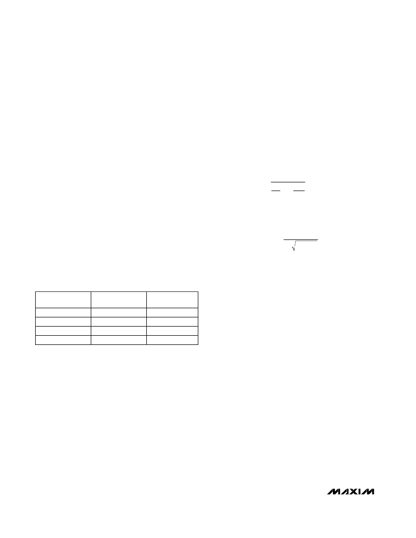
�Power� Management�
�The� MAX2511� features� four� power-supply� modes� to� pre-�
�serve� battery� life.� These� modes� are� selected� via� the�
�RXEN� and� TXEN� pins,� according� to� Table� 1.�
�C� EFF� =�
�2�
�C2�
�1�
�+�
�2�
�C� D1�
�+� C1� +� C� P�
�In� shutdown� mode,� all� part� functions� are� off.� In� standby�
�mode,� the� LO� and� the� LO� buffer� are� active.� This� allows�
�a� PLL� (implemented� externally� to� the� MAX2511)� to�
�remain� up� and� running,� avoiding� any� delay� resulting�
�from� PLL� loop� settling.� Transmit� (Tx)� mode� enables� the�
�LO� circuitry,� upconverter� mixer,� transmit� VGA,� and� out-�
�put� driver� amplifier.� Receive� (Rx)� mode� enables� the� LO�
�circuitry,� downconverter� mixer,� limiting� amplifier,� and�
�adjustable� output� level� amplifier.�
�Table� 1.� Power-Supply� Mode� Selection�
�Using� this� value� for� the� resonant� tank� circuit,� the� oscil-�
�lation� frequency� is� as� follows:�
�1�
�F� OSC� =�
�2� L� 1� C� EFF�
�EMBED� π� Equation.2�
�Starting� with� the� inductor� recommended� in� Table� 2,�
�choose� the� component� values� according� to� your� appli-�
�cation� needs,� such� as� phase� noise,� tuning� range,� and�
�VCO� gain.� Keep� the� tank’s� Q� as� high� as� possible� to�
�RXEN�
�STATE�
�Low�
�Low�
�High�
�High�
�TXEN�
�STATE�
�Low�
�High�
�Low�
�High�
�MODE�
�Shutdown�
�Transmit�
�Receive�
�Standby�
�reduce� phase� noise.� For� most� of� the� MAX2511’s� appli-�
�cations� (such� as� a� first� IF� to� second� IF� transceiver),� the�
�oscillator’s� tuning� range� can� be� quite� small,� since� the� IF�
�frequencies� are� not� tuned� for� channel� selection.� This�
�allows� a� narrowband� oscillator� tank� to� be� used,� which�
�typically� provides� better� phase� noise� and� stability� per-�
�formance� than� wideband� tank� circuits.� Careful� PC�
�board� layout� of� the� oscillator� tank� is� essential.� See� the�
�Layout� Issues� section� for� more� information.�
�__________Applications� Information�
�400MHz� ISM� Applications�
�The� MAX2511� can� be� used� in� applications� where� the�
�200MHz� to� 440MHz� signal� is� an� RF� (rather� than� an� IF)�
�signal,� such� as� in� 400MHz� ISM� applications.� In� this�
�case,� we� recommend� preceding� the� MAX2511� receiver�
�section� with� a� low-noise� amplifier� (LNA)� that� can� oper-�
�ate� over� the� same� supply-voltage� range.� The�
�MAX2630� –MAX2633� family� of� amplifiers� meets� this�
�requirement.� But� since� these� parts� have� single-ended�
�inputs� and� outputs,� it� is� necessary� to� AC� terminate� the�
�unused� MAX2511� input� (� RXIN� )� to� ground� with� 47nF.�
�To� overdrive� the� oscillator� from� an� external� 50� ?� source,�
�see� Figure� 4.�
�Rx� Input� Impedance� Matching�
�The� RXIN,� RXIN� port� typically� needs� an� impedance-�
�matching� network� for� proper� connection� to� external� cir-�
�cuitry� such� as� a� filter.� See� the� Typical� Operating� Circuit�
�for� an� example� circuit� topology.� A� shunt� resistor� across�
�RXIN,� RXIN� can� be� used� to� set� terminating� impedance,�
�with� a� slight� degradation� of� the� Noise� Figure.�
�The� component� values� used� in� the� matching� network�
�depend� on� the� desired� operating� frequency� as� well� as�
�the� filter� impedance.� Table� 3� indicates� the� RXIN,� RXIN�
�differential� input� impedance� in� both� series� and� parallel�
�form.� This� data� is� also� plotted� in� the� Typical� Operating�
�Characteristics.�
�12�
�______________________________________________________________________________________�
�相关PDF资料 |
PDF描述 |
|---|---|
| IXFX15N100 | MOSFET N-CH 1KV 15A PLUS247 |
| B82802A0055A325 | TRANSFORMER FLYBACK 36-60V SMD |
| MAX2510EEI+T | IC TXRX IF W/RSSI&MODLTR 28-QSOP |
| MAX2831ETM+ | IC TXRX 2.4GHZ-2.5GHZ 48TQFN |
| MAX2830ETM+T | IC TXRX RF W/PA AND SW 48-TQFN |
相关代理商/技术参数 |
参数描述 |
|---|---|
| MAX2511EVKIT | 功能描述:射频开发工具 MAX2511 Eval Kit RoHS:否 制造商:Taiyo Yuden 产品:Wireless Modules 类型:Wireless Audio 工具用于评估:WYSAAVDX7 频率: 工作电源电压:3.4 V to 5.5 V |
| MAX2514AWLX#G42 | 制造商:Maxim Integrated Products 功能描述: |
| MAX2514ELX | 功能描述:射频发射器 RoHS:否 制造商:Micrel 类型:ASK Transmitter 封装 / 箱体:SOT-23-6 工作频率:300 MHz to 450 MHz 封装:Reel |
| MAX2514ELX-T | 功能描述:射频发射器 RoHS:否 制造商:Micrel 类型:ASK Transmitter 封装 / 箱体:SOT-23-6 工作频率:300 MHz to 450 MHz 封装:Reel |
| MAX2514EVKIT | 功能描述:射频开发工具 RoHS:否 制造商:Taiyo Yuden 产品:Wireless Modules 类型:Wireless Audio 工具用于评估:WYSAAVDX7 频率: 工作电源电压:3.4 V to 5.5 V |
发布紧急采购,3分钟左右您将得到回复。