- 您现在的位置:买卖IC网 > PDF目录11010 > MAX261BEWG+ (Maxim Integrated Products)IC FILTER ACT MPU PROG 24-SOIC PDF资料下载
参数资料
| 型号: | MAX261BEWG+ |
| 厂商: | Maxim Integrated Products |
| 文件页数: | 11/26页 |
| 文件大小: | 0K |
| 描述: | IC FILTER ACT MPU PROG 24-SOIC |
| 产品培训模块: | Lead (SnPb) Finish for COTS Obsolescence Mitigation Program |
| 标准包装: | 30 |
| 滤波器类型: | 通用开关电容器 |
| 频率 - 截止或中心: | 57kHz |
| 滤波器数: | 2 |
| 滤波器阶数: | 2nd |
| 电源电压: | 4.74 V ~ 12.6 V,±2.37 V ~ 6.3 V |
| 安装类型: | 表面贴装 |
| 封装/外壳: | 24-SOIC(0.295",7.50mm 宽) |
| 供应商设备封装: | 24-SOIC W |
| 包装: | 管件 |
MAX260/MAX261/MAX262
Microprocessor Programmable
Universal Active Filters
______________________________________________________________________________________
19
HOAP = Allpass output gain for DC < f < fCLK / 4
f0 =
ω0 / 2π
Filter Design Procedure
The procedure for most filter designs is to first convert
the required frequency response specifications to f0s
and Qs for the appropriate number of second-order
sections that implement the filter. This can be done by
using design equations or tables in available liter-
ature, or can be conveniently calculated using Maxim's
filter design software. Once the f0s and Qs have been
found, the next step is to turn them into the digital pro-
gram coefficients required by the MAX260/MAX261/
MAX262. An operating mode and clock frequency (or
clock/center frequency ratio) must also be selected.
Next, if the sample rate (fCLK/2) is low enough to cause
significant errors, the selected f0s and Qs should be
corrected to account for sampling effects by using
Figure 20 or Maxim's design software. In most cases,
the sampling errors are small enough to require no cor-
rection, i.e., less than 1%. In any case, with or without
correction, the required f0s and Qs can then be select-
ed from Tables 2 and 3. Maxim's filter design software
Gs
H
s
sQ
ss
Q
OAP
oo
()
(
/
)
(
/
)
=
+
++
2
ωω
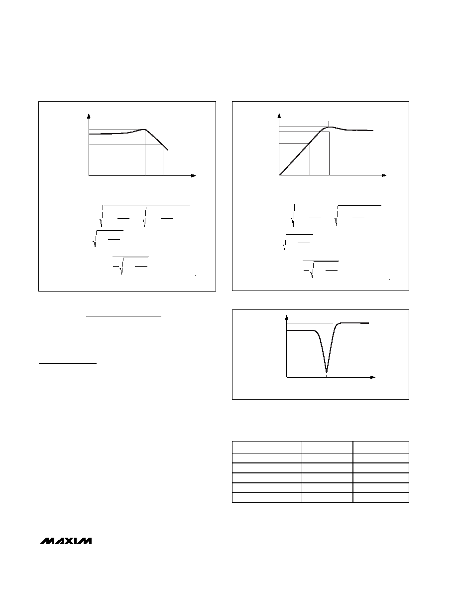
fP
fC
HOP
0.707 HOLP
HOLP
LOWPASS OUTPUT
f(LOG SCALE)
GAIN
(V/V)
Figure 13. Second-Order Lowpass Characteristics
ff
X
QQ
fp
f
Q
HH
X
Q
CO
O
OP
OLP
=
+
+
=
1
2
1
2
1
2
1
4
22
2
fC
fP
HOP
0.707 HOHP
HOHP
HIGHPASS OUTPUT
f(LOG SCALE)
GAIN
(V/V)
Figure 14. Second-Order Highpass Characteristics
ff
X
QQ
fp
f
Q
HH
X
Q
CO
O
OP
OHP
=
+
+
=
1
2
1
2
1
2
1
4
22
2
f(LOG SCALE)
GAIN
(V/V)
fN
HON1
HON
HON2
Figure 15. Second-Order Notch Characteristics
TOTAL SECTIONS
TOTAL B.W.
TOTAL Q
1
1.000 B
1.00 Q
2
0.644 B
1.55 Q
3
0.510 B
1.96 Q
4
0.435 B
2.30 Q
5
0.386 B
2.60 Q
Table 6. Cascading Identical Bandpass
Filter Sections
Note: B = individual stage bandwidth, Q = individual
stage Q.
相关PDF资料 |
PDF描述 |
|---|---|
| MC9S08RG60FGE | IC MCU 60K FLASH 8MHZ 44-LQFP |
| MAX267BEWG+ | IC FILTER BANDPASS PROG 24-SOIC |
| MAX265BEWI+ | IC FILTER ACT PROG 28-SOIC |
| MAX280EWE+ | IC FILTER LOWPASS 16-SOIC |
| MAX264BCWI+ | IC FILTER BANDPASS PROG 28-SOIC |
相关代理商/技术参数 |
参数描述 |
|---|---|
| MAX261BEWG+ | 功能描述:有源滤波器 MPU Programmable Universal RoHS:否 制造商:Maxim Integrated 通道数量:1 截止频率:150 KHz 电源电压-最大:11 V 电源电压-最小:4.74 V 最大工作温度:+ 85 C 安装风格:Through Hole 封装 / 箱体:PDIP N 封装:Tube |
| MAX261BEWG+T | 功能描述:有源滤波器 MPU Programmable Universal RoHS:否 制造商:Maxim Integrated 通道数量:1 截止频率:150 KHz 电源电压-最大:11 V 电源电压-最小:4.74 V 最大工作温度:+ 85 C 安装风格:Through Hole 封装 / 箱体:PDIP N 封装:Tube |
| MAX261BEWG-T | 功能描述:有源滤波器 RoHS:否 制造商:Maxim Integrated 通道数量:1 截止频率:150 KHz 电源电压-最大:11 V 电源电压-最小:4.74 V 最大工作温度:+ 85 C 安装风格:Through Hole 封装 / 箱体:PDIP N 封装:Tube |
| MAX261BMRG | 功能描述:有源滤波器 RoHS:否 制造商:Maxim Integrated 通道数量:1 截止频率:150 KHz 电源电压-最大:11 V 电源电压-最小:4.74 V 最大工作温度:+ 85 C 安装风格:Through Hole 封装 / 箱体:PDIP N 封装:Tube |
| MAX2620E/D | 制造商:Maxim Integrated Products 功能描述:10MHZ TO 1050MHZ INTEGRATED RF OSCILLATOR WITH BUFFERED OUTP - Gel-pak, waffle pack, wafer, diced wafer on film |
发布紧急采购,3分钟左右您将得到回复。