- 您现在的位置:买卖IC网 > PDF目录383349 > MAX2820-MAX2821 (Maxim Integrated Products, Inc.) 2.4GHz 802.11b Zero-IF Transceivers PDF资料下载
参数资料
| 型号: | MAX2820-MAX2821 |
| 厂商: | Maxim Integrated Products, Inc. |
| 英文描述: | 2.4GHz 802.11b Zero-IF Transceivers |
| 中文描述: | 基于2.4GHz 802.11b零IF收发器 |
| 文件页数: | 16/23页 |
| 文件大小: | 392K |
| 代理商: | MAX2820-MAX2821 |

M
2.4GHz 802.11b Zero-IF Transceivers
16
______________________________________________________________________________________
Programmable Registers
The MAX2820/MAX2821 contain programmable regis-
ters to control various modes of operation for the major
circuit blocks. The registers can be programmed
through the 3-wire SPI/QSPI/MICROWIRE-compatible
serial port. The MAX2820/MAX2821 include five pro-
grammable registers:
1) Block-enable register
2) Synthesizer register
3) Channel frequency register
4) Receiver settings register
5) Transmitter settings register
Each register consists of 16 bits. The four most signifi-
cant bits (MSBs) are the register
’
s address. The twelve
least significant bits (LSBs) are used for register data.
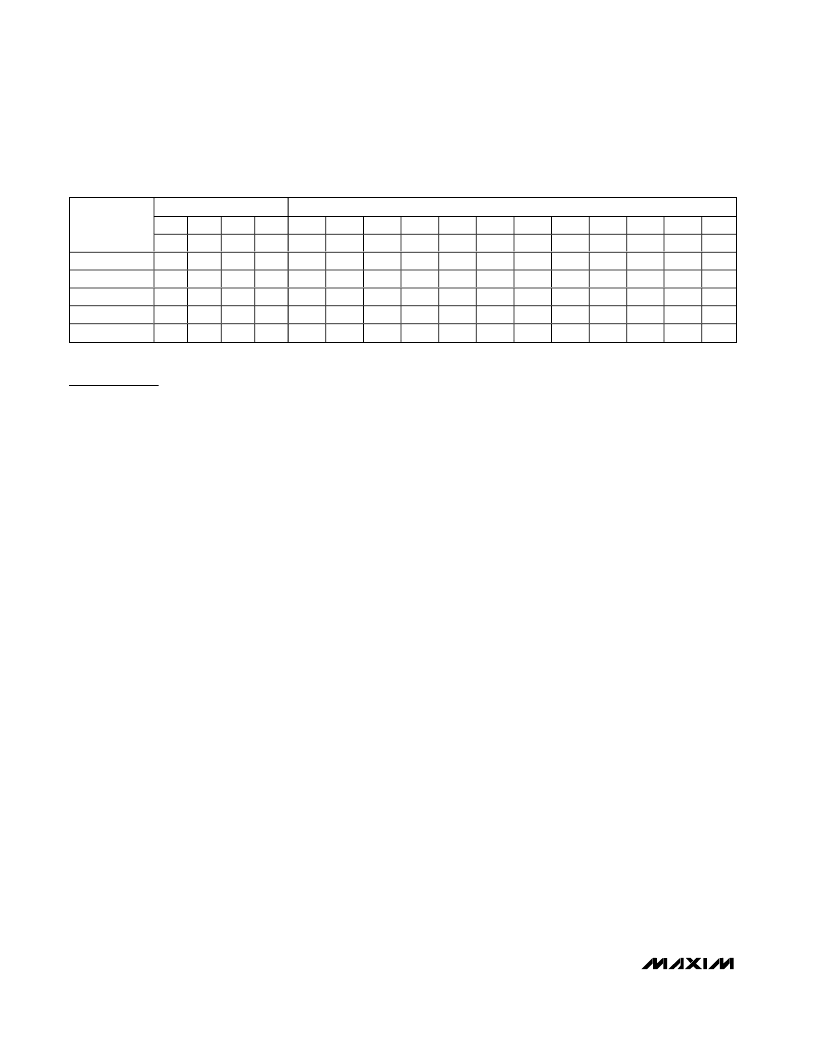
Table 2 summarizes the register configuration. A
detailed description of each register is provided in
Tables 3
–
6.
Data is shifted in the MSB first. The data sent to the
MAX2820/MAX2821, in 16-bit words, is framed by CSB.
When CSB is low, the clock is active and data is shifted
with the rising edge of the clock. When CSB transitions
to high, the shift register is latched into the register
selected by the contents of the address bits. Only the
last 16 bits shifted into the MAX2820/MAX2821 are
retained in the shift register. No check is made on the
number of clock pulses. Figure 1 documents the serial
interface timing for the MAX2820/MAX2821.
Power-Up Default States
The MAX2820/MAX2821 provide power-up loading of
default states for each of the registers. The states are
loaded on a VCC_DIG supply voltage transition from 0V
to V
CC
. The default values are retained until repro-
grammed through the serial interface or the power sup-
ply voltage is taken to 0V. The default state of each
register is described in Table 3.
Note:
Putting the IC in
shutdown mode does not change the contents of the
programming registers.
Block-Enable Register
The block-enable register permits individual control of the
enable state for each major circuit block in the
MAX2820/MAX2821. The actual enable condition of the
circuit block is a logical function of the block-enable bit
setting and other control input states. Table 4 documents
the logical definition of state for each major circuit block.
Synthesizer Register
The synthesizer register (SYNTH) controls the reference
frequency divider and charge-pump current of the PLL.
See Table 5 for a description of the bit settings.
Channel Frequency Register
The channel frequency register (CHANNEL) sets the
RF carrier frequency for the MAX2820/MAX2821. The
channel is programmed as a number from 0 to 99. The
actual frequency is 2400 + channel in MHz. The default
setting is 37 for 2437MHz. See Table 6 for a description
of the bit settings.
Receiver Settings Register
The receive settings register (RECEIVE) controls the
receive filter -3dB corner frequency, RX level detector
midpoint, and VGA DC offset nulling parameters. The
defaults are intended to provide proper operation.
However, the filter frequency and detector can be modi-
fied if desired. Do not reprogram VGA DC offset nulling
parameters. These settings were optimized during devel-
opment. See Table 7 for a description of the bit settings.
Transmitter Settings Register
The transmitter settings register (TRANSMIT) controls
the 4-bit PA bias DAC. The 4 bits correspond to a PA
bias current between 0 and full scale (~300μA). See
Table 8 for the bit settings.
4 ADDRESS BITS
A3
A2
MSB
15
0
0
0
0
0
0
0
1
0
1
12 DATA BITS
D6
7
E6
ICP
CF6
1C0
X
A1
14
0
1
1
0
0
A0
13
1
0
1
0
1
D11
12
E11
X
X
2C2
X
D10
11
E10
X
X
2C1
X
D9
10
E9
X
X
2C0
X
D8
9
E8
X
X
1C2
X
D7
8
E7
PD
X
1C1
X
D5
6
E5
R5
CF5
DL1
X
D4
5
E4
R4
CF4
DL0
X
D3
4
E3
R3
CF3
SF
PA3
D2
3
E2
R2
CF2
BW2
PA2
D1
2
E1
R1
CF1
BW1
PA1
D0
LSB
E0
R0
CF0
BW0
PA0
REGISTER
NAME
ENABLE
SYNTH
CHANNEL
RECEIVE
TRANSMIT
Table 2. Programming Register Definition Summary (Address and Data)
X = Don
’
t care.
相关PDF资料 |
PDF描述 |
|---|---|
| MAX2820EGM-TD | 2.4GHz 802.11b Zero-IF Transceivers |
| MAX2825EVKIT | Evaluation Kits for the MAX2825/MAX2826/MAX2827 |
| MAX2826EVKIT | Evaluation Kits for the MAX2825/MAX2826/MAX2827 |
| MAX2827EVKIT | Evaluation Kits for the MAX2825/MAX2826/MAX2827 |
| MAX2825 | POT 50K OHM 12MM VERT NO BUSHING |
相关代理商/技术参数 |
参数描述 |
|---|---|
| MAX2821AETM | 功能描述:射频接收器 RoHS:否 制造商:Skyworks Solutions, Inc. 类型:GPS Receiver 封装 / 箱体:QFN-24 工作频率:4.092 MHz 工作电源电压:3.3 V 封装:Reel |
| MAX2821AETM+ | 功能描述:射频接收器 RF and RFID RoHS:否 制造商:Skyworks Solutions, Inc. 类型:GPS Receiver 封装 / 箱体:QFN-24 工作频率:4.092 MHz 工作电源电压:3.3 V 封装:Reel |
| MAX2821AETM+D | 功能描述:射频接收器 RoHS:否 制造商:Skyworks Solutions, Inc. 类型:GPS Receiver 封装 / 箱体:QFN-24 工作频率:4.092 MHz 工作电源电压:3.3 V 封装:Reel |
| MAX2821AETM+T | 功能描述:射频接收器 RF and RFID RoHS:否 制造商:Skyworks Solutions, Inc. 类型:GPS Receiver 封装 / 箱体:QFN-24 工作频率:4.092 MHz 工作电源电压:3.3 V 封装:Reel |
| MAX2821AETM+TD | 功能描述:射频接收器 RoHS:否 制造商:Skyworks Solutions, Inc. 类型:GPS Receiver 封装 / 箱体:QFN-24 工作频率:4.092 MHz 工作电源电压:3.3 V 封装:Reel |
发布紧急采购,3分钟左右您将得到回复。