- 您现在的位置:买卖IC网 > PDF目录9864 > MAX3190EUT+T (Maxim Integrated Products)IC RS-232 TRANSMITTER SOT23-6 PDF资料下载
参数资料
| 型号: | MAX3190EUT+T |
| 厂商: | Maxim Integrated Products |
| 文件页数: | 5/8页 |
| 文件大小: | 0K |
| 描述: | IC RS-232 TRANSMITTER SOT23-6 |
| 产品培训模块: | Lead (SnPb) Finish for COTS Obsolescence Mitigation Program |
| 标准包装: | 2,500 |
| 类型: | 发射器 |
| 驱动器/接收器数: | 1/0 |
| 规程: | RS232 |
| 电源电压: | 4.5 V ~ 6 V |
| 安装类型: | 表面贴装 |
| 封装/外壳: | SOT-23-6 |
| 供应商设备封装: | SOT-6 |
| 包装: | 带卷 (TR) |
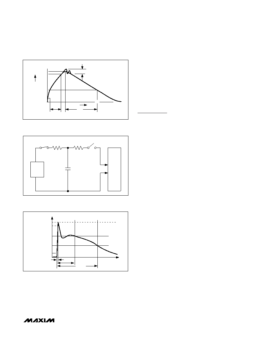
shows the current waveform for the ±8kV IEC 1000-4-2
Level 4 ESD Contact Discharge test. The Air-Gap test
involves approaching the device with a charged probe.
The Contact Discharge method connects the probe to
the device before the probe is energized.
Power-Supply Decoupling
In most circumstances, 0.1F bypass capacitors are
adequate for power-supply decoupling. Connect the
bypass capacitors as close to the IC as possible.
Applications Information
Power-Supply Sources
The MAX3190/MAX3190E require ±7.5V to ±12V dual
supplies. For applications where these supply voltages
are not present, a DC-DC converter must be added.
Due to the MAX3190/MAX3190E’s low current con-
sumption, a charge pump can provide the proper supply
voltages and requires a minimal amount of board
space and cost.
When using another RS-232 device containing an internal
unregulated charge pump (Tables 1 and 2), the
MAX3190/MAX3190E may be powered from the internal
charge pump (Figure 6). This eliminates the need for
additional external DC-DC converters to generate the
required ±7.5V to ±12V dual supplies. The MAX3190/
MAX3190E are specifically designed to be used with
Maxim’s RS-232 products listed in Tables 1 and 2.
Competitive RS-232 devices’ charge pumps typically
do not have the capability to power these devices.
The MAX3190/MAX3190E can be operated from ±6V to
±7.5V supplies. In this condition, the devices are guar-
anteed to be RS-232-compatible (TOUT
≥ +3.7V).
For applications that have ±4.5V to ±6V supplies avail-
able, please refer to the MAX3188/MAX3189 or
MAX3188E/MAX3189E data sheet.
MAX3190/MAX3190E
±15kV ESD-Protected, 460kbps,
RS-232 Transmitters in SOT23-6
_______________________________________________________________________________________
5
IP 100%
90%
36.8%
tRI
TIME
tDL
CURRENT WAVEFORM
PEAK-TO-PEAK RINGING
(NOT DRAWN TO SCALE)
Ir
10%
0
AMPERES
Figure 3. Human Body Model Current Waveform
CHARGE-CURRENT
LIMIT RESISTOR
DISCHARGE
RESISTANCE
STORAGE
CAPACITOR
Cs
150pF
RC
50M
TO 100M
RD
330
HIGH-
VOLTAGE
DC
SOURCE
DEVICE
UNDER
TEST
Figure 4. IEC 1000-4-2 ESD Test Model
tR = 0.7ns TO 1ns
30ns
60ns
t
100%
90%
10%
I PEAK
I
Figure 5. IEC 1000-4-2 Generator Current Waveform
相关PDF资料 |
PDF描述 |
|---|---|
| VE-B5J-MW-F4 | CONVERTER MOD DC/DC 36V 100W |
| VE-B5J-MW-F3 | CONVERTER MOD DC/DC 36V 100W |
| MAX153EAP+ | IC ADC 8BIT 1MSPS HI-SPD 20-SSOP |
| GTC02R-24-2P | CONN RCPT 7POS BOX MNT W/PINS |
| MAX150BCWP+ | IC ADC 8BIT W/REF T/H 20-SOIC |
相关代理商/技术参数 |
参数描述 |
|---|---|
| MAX31910AUI+ | 制造商:Maxim Integrated Products 功能描述:- Rail/Tube |
| MAX31910AUI+T | 制造商:Maxim Integrated Products 功能描述:- Tape and Reel |
| MAX31911AHI+ | 制造商:Maxim Integrated Products 功能描述:- Rail/Tube |
| MAX31911AHI+T | 制造商:Maxim Integrated Products 功能描述:- Tape and Reel |
| MAX31911AUI+ | 功能描述:串行器/解串器 - Serdes Octal Industrial Digital Serializer RoHS:否 制造商:Texas Instruments 类型:Deserializer 数据速率:1.485 Gbit/s 输入类型:ECL/LVDS 输出类型:LVCMOS 输入端数量:1 输出端数量:20 工作电源电压:2.375 V to 2.625 V 工作温度范围:0 C to + 70 C 封装 / 箱体:TQFP-64 |
发布紧急采购,3分钟左右您将得到回复。