- 您现在的位置:买卖IC网 > PDF目录9796 > MAX3241CWI+T (Maxim Integrated Products)IC TXRX RS-232 LP 28-SOIC PDF资料下载
参数资料
| 型号: | MAX3241CWI+T |
| 厂商: | Maxim Integrated Products |
| 文件页数: | 16/17页 |
| 文件大小: | 0K |
| 描述: | IC TXRX RS-232 LP 28-SOIC |
| 产品培训模块: | Lead (SnPb) Finish for COTS Obsolescence Mitigation Program |
| 标准包装: | 1,000 |
| 类型: | 收发器 |
| 驱动器/接收器数: | 3/5 |
| 规程: | RS232 |
| 电源电压: | 3 V ~ 5.5 V |
| 安装类型: | 表面贴装 |
| 封装/外壳: | 28-SOIC(0.295",7.50mm 宽) |
| 供应商设备封装: | 28-SOIC W |
| 包装: | 带卷 (TR) |

MAX3222/MAX3232/MAX3237/MAX3241
3.0V to 5.5V, Low-Power, up to 1Mbps, True RS-232
Transceivers Using Four 0.1F External Capacitors
8
_______________________________________________________________________________________
RS-232 Receivers
The receivers convert RS-232 signals to CMOS-logic out-
put levels. The MAX3222/MAX3237/MAX3241 receivers
have inverting three-state outputs. In shutdown, the
receivers can be active or inactive (Table 1).
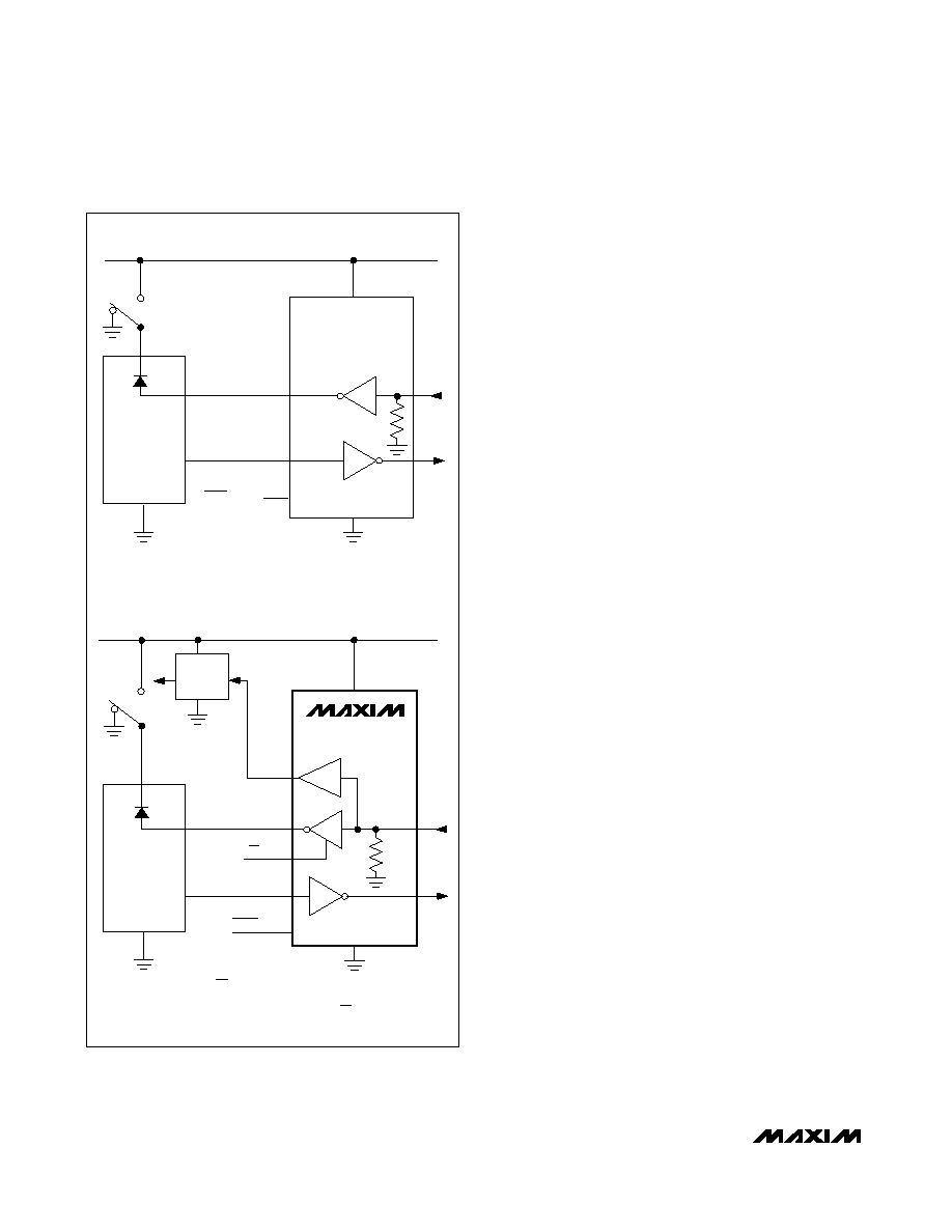
The complementary outputs on the MAX3237 (R1OUTB)
and the MAX3241 (R1OUTB, R2OUTB) are always active,
regardless of the state of EN or SHDN. This allows for
Ring Indicator applications without forward biasing other
devices connected to the receiver outputs. This is ideal
for systems where VCC is set to 0V in shutdown to
accommodate peripherals, such as UARTs (Figure 2).
MAX3222/MAX3237/MAX3241
Shutdown Mode
Supply current falls to less than 1A in shutdown mode
(SHDN = low). When shut down, the device’s charge
pumps are turned off, V+ is pulled down to VCC, V- is
pulled to ground, and the transmitter outputs are dis-
abled (high impedance). The time required to exit shut-
down is typically 100s, as shown in Figure 3. Connect
SHDN to VCC if the shutdown mode is not used. SHDN
has no effect on R_OUT or R_OUTB.
MAX3222/MAX3237/MAX3241
Enable Control
The inverting receiver outputs (R_OUT) are put into a
high-impedance state when EN is high. The complemen-
tary outputs R1OUTB and R2OUTB are always active,
regardless of the state of EN and SHDN (Table 1). EN
has no effect on T_OUT.
__________Applications Information
Capacitor Selection
The capacitor type used for C1–C4 is not critical for
proper operation; polarized or nonpolarized capacitors
can be used. The charge pump requires 0.1F capaci-
tors for 3.3V operation. For other supply voltages, refer to
Table 2 for required capacitor values. Do not use values
lower than those listed in Table 2. Increasing the capaci-
tor values (e.g., by a factor of 2) reduces ripple on the
transmitter outputs and slightly reduces power consump-
tion. C2, C3, and C4 can be increased without changing
C1’s value. However, do not increase C1 without also
increasing the values of C2, C3, and C4, to maintain the
proper ratios (C1 to the other capacitors).
When using the minimum required capacitor values,
make sure the capacitor value does not degrade exces-
sively with temperature. If in doubt, use capacitors with a
higher nominal value. The capacitor’s equivalent series
resistance (ESR), which usually rises at low tempera-
tures, influences the amount of ripple on V+ and V-.
MAX3237
MAX3241
T1OUT
R1OUTB
Tx
UART
VCC
T1IN
LOGIC
TRANSITION
DETECTOR
R1IN
R1OUT
EN = VCC
SHDN = GND
VCC
TO
P
Rx
PREVIOUS
RS-232
Tx
UART
PROTECTION
DIODE
PROTECTION
DIODE
SHDN = GND
VCC
GND
Rx
5k
a) OLDER RS-232: POWERED-DOWN UART DRAWS CURRENT FROM
ACTIVE RECEIVER OUTPUT IN SHUTDOWN.
b) NEW MAX3237/MAX3241: EN SHUTS DOWN RECEIVER OUTPUTS (EXCEPT FOR
B OUTPUTS), SO NO CURRENT FLOWS TO UART IN SHUTDOWN. B OUTPUTS
INDICATE RECEIVER ACTIVITY DURING SHUTDOWN WITH EN HIGH.
GND
5k
Figure 2. Detection of RS-232 Activity when the UART and
Interface are Shut Down; Comparison of MAX3237/MAX3241
(b) with Previous Transceivers (a).
相关PDF资料 |
PDF描述 |
|---|---|
| VI-23M-IU-F4 | CONVERTER MOD DC/DC 10V 200W |
| MAX485EEPA+G104 | IC TXRX RS485/RS422 8-DIP |
| MS27484E8B35SA | CONN PLUG 6POS STRAIGHT W/SCKT |
| MS27484E20B35PC | CONN PLUG 79POS STRAIGHT W/PINS |
| VI-23L-IU-F2 | CONVERTER MOD DC/DC 28V 200W |
相关代理商/技术参数 |
参数描述 |
|---|---|
| MAX3241EAI | 功能描述:RS-232接口集成电路 RoHS:否 制造商:Exar 数据速率:52 Mbps 工作电源电压:5 V 电源电流:300 mA 工作温度范围:- 40 C to + 85 C 安装风格:SMD/SMT 封装 / 箱体:LQFP-100 封装: |
| MAX3241EAI+ | 功能描述:RS-232接口集成电路 3-5.5V 235kbps Transceiver RoHS:否 制造商:Exar 数据速率:52 Mbps 工作电源电压:5 V 电源电流:300 mA 工作温度范围:- 40 C to + 85 C 安装风格:SMD/SMT 封装 / 箱体:LQFP-100 封装: |
| MAX3241EAI+T | 功能描述:RS-232接口集成电路 3-5.5V 235kbps Transceiver RoHS:否 制造商:Exar 数据速率:52 Mbps 工作电源电压:5 V 电源电流:300 mA 工作温度范围:- 40 C to + 85 C 安装风格:SMD/SMT 封装 / 箱体:LQFP-100 封装: |
| MAX3241EAI-T | 功能描述:RS-232接口集成电路 RoHS:否 制造商:Exar 数据速率:52 Mbps 工作电源电压:5 V 电源电流:300 mA 工作温度范围:- 40 C to + 85 C 安装风格:SMD/SMT 封装 / 箱体:LQFP-100 封装: |
| MAX3241ECAI | 功能描述:RS-232接口集成电路 RoHS:否 制造商:Exar 数据速率:52 Mbps 工作电源电压:5 V 电源电流:300 mA 工作温度范围:- 40 C to + 85 C 安装风格:SMD/SMT 封装 / 箱体:LQFP-100 封装: |
发布紧急采购,3分钟左右您将得到回复。