- 您现在的位置:买卖IC网 > PDF目录10517 > MAX3345EEUE+ (Maxim Integrated Products)IC USB TXRX W/DETECT 16-TSSOP PDF资料下载
参数资料
| 型号: | MAX3345EEUE+ |
| 厂商: | Maxim Integrated Products |
| 文件页数: | 13/15页 |
| 文件大小: | 0K |
| 描述: | IC USB TXRX W/DETECT 16-TSSOP |
| 产品培训模块: | Lead (SnPb) Finish for COTS Obsolescence Mitigation Program |
| 标准包装: | 96 |
| 类型: | 收发器 |
| 驱动器/接收器数: | 1/1 |
| 规程: | USB 2.0 |
| 电源电压: | 4 V ~ 5.5 V |
| 安装类型: | 表面贴装 |
| 封装/外壳: | 16-TSSOP(0.173",4.40mm 宽) |
| 供应商设备封装: | 16-TSSOP |
| 包装: | 管件 |
| 产品目录页面: | 1407 (CN2011-ZH PDF) |
Power-Supply Configurations
Normal Operating Mode
Connect VL and VCC to system power supplies (Table
1). Connect VL to a +1.65V to +3.6V supply. Connect
VCC to a +4.0V to +5.5V supply. Alternatively, the
MAX3344E/MAX3345E can derive power from a single
Li+ battery. Connect the battery to VCC. VVTRM remains
above +3.0V for VCC as low as +3.1V.
Additionally, the MAX3344E/MAX3345E can derive
power from a 3.3V ±10% voltage regulator. Connect VCC
and VTRM to an external +3.3V voltage regulator.
Disable Mode
Connect VCC to a system power supply and leave VL
unconnected or connect to GND. D+ and D- enter a tri-
state mode and VCC consumes less than 20A of supply
current. D+ and D- withstand external signals up to
+5.5V in disable mode (Table 2).
Sharing Mode
Connect VL to a system power supply and leave VCC (or
VCC and VTRM) unconnected or connect to GND. D+
and D- enter a tri-state mode, allowing other circuitry to
share the USB D+ and D- lines, and VL consumes less
than 20A of supply current. D+ and D- withstand exter-
nal signals up to +5.5V in sharing mode (Table 2).
Device Control
D+ and D-
D+ and D- are the USB-side transmitter I/O connec-
tions, and are ESD protected to ±15kV using the
Human Body Model, ±10kV using IEC 1000-4-2 Air-
Gap Discharge, and ±8kV using IEC 1000-4-2 Contact
Discharge, making the MAX3344E/MAX3345E ideal for
applications where a robust transmitter is required. A
23.7 resistor is required on D+ and D- for normal
operation (see the External Resistors section).
ENUM
USB specification 2.0 requires a 1.5k pullup resistor
on D+ for full-speed (12Mbps) operation. Controlled by
enumerate (ENUM), the MAX3344E/MAX3345E provide
this internal 1.5k resistor. Drive ENUM high to connect
the pullup resistor from D+ to VTRM. Drive ENUM low to
disconnect the pullup resistor from D+ to VTRM.
VPO/VMO, VPI/VMI, and OE
The MAX3344E/MAX3345E system-side inputs are VPO
and VMO. Data comes into the MAX3344E/MAX3345E
through VPO and VMO. VPO and VMO operate either
differentially with VPO as the positive terminal and VMO
as the negative terminal, or single ended with VPO as
the data input (see the MODE section).
MAX3344E/MAX3345E
±15kV ESD-Protected USB Transceivers
in UCSP with USB Detect
_______________________________________________________________________________________
7
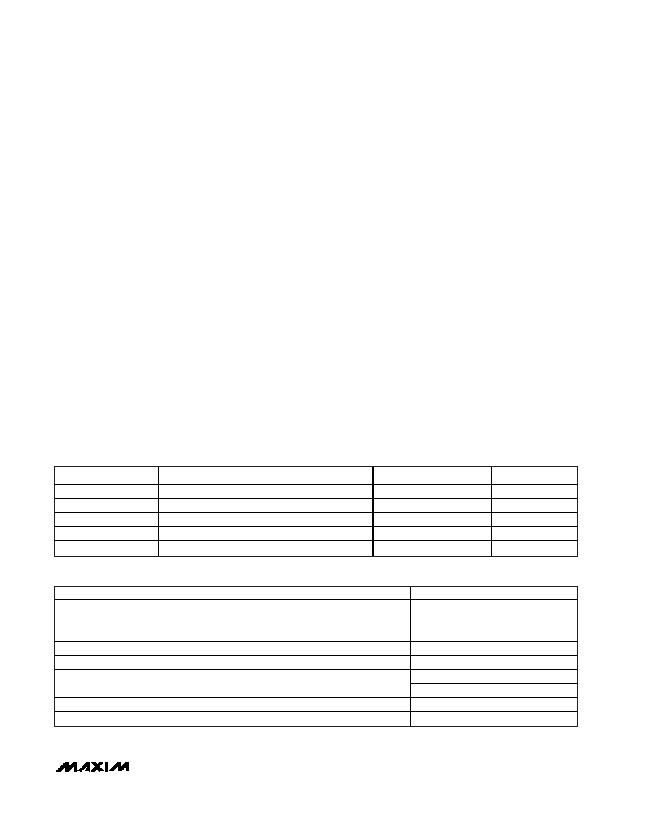
VCC (V)
VTRM (V)
VL (V)
CONFIGURATION
NOTES
+4.0 to +5.5
+3.3 Output
+1.65 to +3.6
Normal mode
—
+3.1 to +4.5
+3.3 Output
+1.65 to +3.6
Battery supply
—
+3.0 to +3.6
+3.0 to +3.6 Input
+1.65 to +3.6
Voltage regulator supply
—
GND or floating
Output
+1.65 to +3.6
Sharing mode
Table 2
+3.0 to +5.5
Output
GND or floating
Disable mode
Table 2
INPUTS/OUTPUTS
DISABLE MODE
SHARING MODE
VCC/VTRM
+5V input/+3.3V output
+3.3V input/+3.3V input
+3.7V input/+3.3V output
Floating or connected to GND
< +3.6V (MAX3344E)
< +1.0V (MAX3345E)
VL
Floating or connected to GND
+1.65V to +3.6V input
D+ and D-
High impedance
High impedance for
OE = Low
VPI and VMI
Invalid*
High for
OE = High
RCV
Invalid*
Undefined**
SPEED, SUSP,
OE, ENUM
High impedance
Table 2. Disable-Mode and Sharing-Mode Configurations
Table 1. Power-Supply Configurations
*High Impedance or low.
**High or low.
相关PDF资料 |
PDF描述 |
|---|---|
| MAX3032ECSE+ | IC RS-422 TRANSMIT QUAD 16-SOIC |
| MAX3344EEUE+ | IC USB TXRX W/DETECT 16-TSSOP |
| AD977ABRSZ | IC ADC 16BIT 200KSPS 28-SSOP |
| UP050B391K-KFC | CAP CER 390PF 50V 10% AXIAL |
| MAX3454EETE+ | IC TXRX USB ESD-PROT 16TQFN |
相关代理商/技术参数 |
参数描述 |
|---|---|
| MAX3345EEUE+ | 功能描述:USB 接口集成电路 ESD-Protected USB Tcvr RoHS:否 制造商:Cypress Semiconductor 产品:USB 2.0 数据速率: 接口类型:SPI 工作电源电压:3.15 V to 3.45 V 工作电源电流: 最大工作温度:+ 85 C 安装风格:SMD/SMT 封装 / 箱体:WLCSP-20 |
| MAX3345EEUE+T | 功能描述:USB 接口集成电路 ESD-Protected USB Tcvr RoHS:否 制造商:Cypress Semiconductor 产品:USB 2.0 数据速率: 接口类型:SPI 工作电源电压:3.15 V to 3.45 V 工作电源电流: 最大工作温度:+ 85 C 安装风格:SMD/SMT 封装 / 箱体:WLCSP-20 |
| MAX3345EEUE-T | 功能描述:USB 接口集成电路 RoHS:否 制造商:Cypress Semiconductor 产品:USB 2.0 数据速率: 接口类型:SPI 工作电源电压:3.15 V to 3.45 V 工作电源电流: 最大工作温度:+ 85 C 安装风格:SMD/SMT 封装 / 箱体:WLCSP-20 |
| MAX3346EEBE | 制造商:Maxim Integrated Products 功能描述:+/-15KV ESD-PROTECTED USB TRANSCEIV - Rail/Tube |
| MAX3346EEBE+ | 制造商:Maxim Integrated Products 功能描述:+/-15KV ESD-PROTECTED USB TRANSCEIV - Rail/Tube |
发布紧急采购,3分钟左右您将得到回复。