- 您现在的位置:买卖IC网 > PDF目录1228 > MAX34561EVKIT# (Maxim Integrated Products)EVAL KIT DUAL E-FUSE 24-TQFN PDF资料下载
参数资料
| 型号: | MAX34561EVKIT# |
| 厂商: | Maxim Integrated Products |
| 文件页数: | 7/11页 |
| 文件大小: | 0K |
| 描述: | EVAL KIT DUAL E-FUSE 24-TQFN |
| 标准包装: | 1 |
| 系列: | * |
�� �
�
�12V/5V� Hot-Plug� Switch�
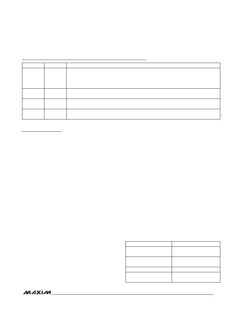
�Pin� Description� (continued)�
�PIN�
�22�
�23�
�24�
�—�
�NAME�
�ARD5�
�VRAMP5�
�TIMER5�
�EP�
�FUNCTION�
�5V� Autoretry� Disable.� Connect� this� pin� to� GND� to� disable� automatic� retry� functionality;� the� device�
�latches� off� during� an� overtemperature� fault.� Leave� this� pin� open� to� enable� automatic� retry� function.�
�This� pin� contains� a� pullup� (R� PU5� )� to� V� CC5� .� This� pin� is� only� sampled� on� device� power-on.� If� the� 5V�
�side� is� not� used,� connect� this� pin� to� GND.�
�5V� Voltage� Ramp� Control.� A� capacitor� connected� to� this� pin� determines� the� voltage� ramp� of� the�
�LOAD5� output� during� turn-on� according� to� the� equation:� dV� LOAD5� =� 2.3332� x� (I� VRAMP� /C� VRAMP5� ).�
�5V� Enable� Delay� Control.� A� capacitor� connected� to� this� pin� determines� the� enable� delay� according�
�to� the� equation:� Enable� Delay� =� C� TIMER5� x� (V� REF5� /I� TIMER� ).�
�Exposed� Pad.� Connect� to� ground.� The� EP� must� be� soldered� to� ground� for� proper� thermal� and� elec-�
�trical� operation.�
�Detailed� Description�
�The� MAX34561� has� hot-plug� controls� for� both� +12V� and�
�+5V� power� rails.� The� circuitry� for� the� +12V� and� +5V� con-�
�trols� are� independent� of� each� other� and� can� be� treated�
�as� two� separate� hot-plug� switches,� even� though� the� GND�
�pin� is� common� between� the� two� switches.� The� sections�
�that� follow� are� written� from� the� +12V� circuit� perspective,�
�but� also� apply� for� the� +5V� switch� control.�
�The� device� begins� to� operate� when� the� supply� voltage�
�V� CC12� (or� V� CC5� )� exceeds� its� undervoltage� lockout� level,�
�V� UR12� (or� V� UR5� ).� At� this� level,� the� corresponding� enable�
�circuit� and� TIMER12� (TIMER5)� become� active.� Once� the�
�device� has� been� enabled,� a� gate� voltage� is� applied� to�
�the� corresponding� power� MOSFET,� allowing� current� to�
�begin� flowing� from� V� CC12� (V� CC5� )� to� LOAD12� (LOAD5).�
�The� speed� of� the� output-voltage� ramp� is� controlled� by�
�the� capacitance� placed� at� the� VRAMP12� (VRAMP5)� pin.�
�The� load� current� is� continuously� monitored� during� the�
�initial� conduction� (I� SCL12� or� I� SCL5� )� and� after� the� cor-�
�responding� MOSFET� is� fully� on� (I� OVL12� or� I� OVL5� ).� If� the�
�current� exceeds� the� current� limit� that� is� set� by� the� exter-�
�nal� resistance� at� ILIM12� (ILIM5),� the� gate� voltage� of� the�
�corresponding� power� MOSFET� is� decreased,� reducing�
�the� output� current� to� the� set� current� limit.�
�When� the� output� power� is� initially� ramping� up,� the� current�
�limit� is� I� SCL12� (I� SCL5� ).� Once� the� corresponding� MOSFET�
�is� fully� on,� the� current� limit� is� I� OVL12� (I� OVL5� ).� The� I� SCL12�
�(I� SCL5� )� current� limit� protects� the� source� if� there� is� a� dead�
�short� on� initial� power-up.�
�The� device� acts� as� a� fuse� and� automatically� disables� the�
�current� flowing� to� the� load� when� the� temperature� of� the�
�power� corresponding� MOSFET� has� exceeded� the� shut-�
�down� junction� temperature,� T� SHDN� .�
�Enable/Timer�
�The� voltage� level� of� TIMER12� (TIMER5)� is� compared� to�
�an� internal� source� (see� the� Functional� Diagram� ).� When�
�the� level� on� the� pin� exceeds� V� ON� ,� the� comparator� out-�
�puts� a� low� level.� This� then� turns� on� the� voltage� ramp�
�circuit,� enabling� the� device’s� output.� TIMER12� (TIMER5)�
�can� be� configured� into� one� of� four� different� modes� of�
�operation� as� listed� in� Table� 1.� TIMER12� (TIMER5)� pin�
�was� designed� to� work� with� most� logic� families.� TIMER12�
�(TIMER5)� has� at� least� 250mV� of� hysteresis� between� V� ON�
�and� V� OFF� .� It� is� recommended� that� any� logic� gate� used�
�to� drive� TIMER12� (TIMER5)� be� tested� to� ensure� proper�
�operation.�
�Table_1._TIMER__Pin_Modes�
�Current� is� limited� by� the� device� comparing� the� volt-�
�age� difference� between� LOAD12� (LOAD5)� and� ILIM12�
�(ILIM5)� to� an� internal� reference� voltage.� If� the� output� cur-�
�rent� exceeds� the� limit� that� is� set� by� the� R� ILIM12� (R� ILIM5� )�
�resistor,� the� gate� voltage� of� the� corresponding� power�
�MOSFET� is� decreased,� which� reduces� the� output� current�
�to� the� load.�
�OPERATION_MODE�
�Automatic� Enable�
�Delayed� Automatic� Enable�
�Enable/Disable�
�Enable� with� Delay/Disable�
�TIMER_PIN_SETUP�
�No� connection� to� TIMER12�
�(TIMER5)�
�Capacitor� C� TIMER_� connected�
�to� TIMER12� (TIMER5)�
�Open-collector� device�
�Open-collector� device� and�
�C� TIMER� _�
�7�
�相关PDF资料 |
PDF描述 |
|---|---|
| MAX34565EVKIT# | KIT EVAL FOR MAX34565 |
| MAX367CWN | IC SIGNAL-LINE CIRC PROT 18-SOIC |
| MAX4080EVKIT+ | KIT EVAL FOR MAX4080 |
| MAX4208EVKIT+ | KIT EVAL FOR MAX4208 |
| MAX4209EVKIT+ | KIT EVAL FOR MAX4209 |
相关代理商/技术参数 |
参数描述 |
|---|---|
| MAX34561EVKIT# | 功能描述:电源管理IC开发工具 12V&5V DUAL E-FUSE RoHS:否 制造商:Maxim Integrated 产品:Evaluation Kits 类型:Battery Management 工具用于评估:MAX17710GB 输入电压: 输出电压:1.8 V |
| MAX34561T+ | 功能描述:热插拔功率分布 12V/5V Hot-Plug Switch RoHS:否 制造商:Texas Instruments 产品:Controllers & Switches 电流限制: 电源电压-最大:7 V 电源电压-最小:- 0.3 V 工作温度范围: 功率耗散: 安装风格:SMD/SMT 封装 / 箱体:MSOP-8 封装:Tube |
| MAX34561T+T | 功能描述:热插拔功率分布 12V/5V Hot-Plug Switch RoHS:否 制造商:Texas Instruments 产品:Controllers & Switches 电流限制: 电源电压-最大:7 V 电源电压-最小:- 0.3 V 工作温度范围: 功率耗散: 安装风格:SMD/SMT 封装 / 箱体:MSOP-8 封装:Tube |
| MAX34564AETB+ | 功能描述:热插拔功率分布 12V Hot Plug Switch Auto-Retry RoHS:否 制造商:Texas Instruments 产品:Controllers & Switches 电流限制: 电源电压-最大:7 V 电源电压-最小:- 0.3 V 工作温度范围: 功率耗散: 安装风格:SMD/SMT 封装 / 箱体:MSOP-8 封装:Tube |
| MAX34564AETB+T | 功能描述:热插拔功率分布 12V Hot Plug Switch Auto-Retry RoHS:否 制造商:Texas Instruments 产品:Controllers & Switches 电流限制: 电源电压-最大:7 V 电源电压-最小:- 0.3 V 工作温度范围: 功率耗散: 安装风格:SMD/SMT 封装 / 箱体:MSOP-8 封装:Tube |
发布紧急采购,3分钟左右您将得到回复。