- 您现在的位置:买卖IC网 > Datasheet目录474 > MAX3543EVKIT+ (Maxim Integrated)EVAL KIT MAX3543 Datasheet资料下载
参数资料
| 型号: | MAX3543EVKIT+ |
| 厂商: | Maxim Integrated |
| 文件页数: | 18/20页 |
| 文件大小: | 0K |
| 描述: | EVAL KIT MAX3543 |
| 标准包装: | 1 |
| 系列: | * |
�� �
�
�Multiband� Analog� and�
�Digital� Television� Tuner�
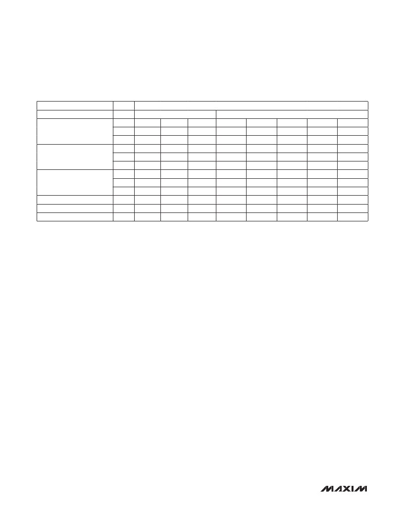
�Table 26. ROM Tabl� e�
�BIAS�
�DESCRIPTION�
�ADDR� MSB�
�0x0�
�Unused�
�DATA� BYTE�
�BIAS[3:0]�
�LSB�
�VHF-Low� Tracking� Filter.�
�VLS0,� VLS1,� VLP0,� VLP1�
�VHF-High� Tracking� Filter.�
�VHS0,� VHS1,� VHP0,� VHP1�
�UHF� Tracking� Filter.�
�US0,� US1,� UP0,� UP1�
�IF� Filter�
�IRHR�
�0x1�
�0x2�
�0x3�
�0x4�
�0x5�
�0x6�
�0x7�
�0x8�
�0x9�
�0xA�
�0xB�
�VLS0[5]�
�VLS1[3]�
�VLP0[1]�
�VHS0[5]�
�VHS1[3]�
�VHP0[1]�
�US0[5]�
�US1[3]�
�UP0[1]�
�Unused�
�IRHR[7]�
�VLS0[4]�
�VLS1[2]�
�VLP0[0]�
�VHS0[4]�
�VHS1[2]�
�VHP0[0]�
�US0[4]�
�US1[2]�
�UP0[0]�
�Unused�
�IRHR[6]�
�VLS0[3]�
�VLS1[1]�
�VLP1[5]�
�VHS0[3]�
�VHS1[1]�
�VHP1[5]�
�US0[3]�
�US1[1]�
�UP1[5]�
�C[5]�
�IRHR[5]�
�VLS0[2]�
�VLS1[0]�
�VLP1[4]�
�VHS0[2]�
�VHS1[0]�
�VHP1[4]�
�US0[2]�
�US1[0]�
�UP1[4]�
�C[4]�
�IRHR[4]�
�VLS0[1]�
�VLP0[5]�
�VLP1[3]�
�VHS0[1]�
�VHP0[5]�
�VHP1[3]�
�US0[1]�
�UP0[5]�
�UP1[3]�
�C[3]�
�IRHR[3]�
�VLS0[0]�
�VLP0[4]�
�VLP1[2]�
�VHS0[0]�
�VHP0[4]�
�VHP1[2]�
�US0[0]�
�UP0[4]�
�UP1[2]�
�C[2]�
�IRHR[2]�
�VLS1[5]�
�VLP0[3]�
�VLP1[1]�
�VHS1[5]�
�VHP0[3]�
�VHP1[1]�
�US1[5]�
�UP0[3]�
�UP1[1]�
�C[1]�
�IRHR[1]�
�VLS1[4]�
�VLP0[2]�
�VLP1[0]�
�VHS1[4]�
�VHP0[2]�
�VHP1[0]�
�US1[4]�
�UP0[2]�
�UP1[0]�
�C[0]�
�IRHR[0]�
�Reserved�
�0xC�
�Reserved Reserved� Reserved� Reserved�
�Reserved�
�Reserved�
�Reserved�
�Reserved�
�Setting� RF� Tracking� Filter� Codes�
�The� MAX3543� includes� a� programmable� tracking� filter�
�for� each� band� of� operation� to� optimize� rejection� of� out-�
�of-band� interference� while� minimizing� insertion� loss� for�
�the� desired� received� signal.� The� center� frequency� of�
�each� tracking� filter� is� selected� by� a� switched-capacitor�
�array� that� is� programmed� by� the� TFS[7:0]� bits� in� the� R06�
�register� and� the� TFP[5:0]� bits� in� the� R07� register.�
�Optimal� tracking� filter� settings� for� each� channel� vary� from�
�part� to� part� due� to� process� variations.� To� accommodate�
�part-to-part� variations,� each� part� is� factory� calibrated� by�
�Maxim.� During� calibration� the� correction� factors� for� the�
�series� and� parallel� tracking� capacitor� arrays� are� calculat-�
�ed� and� written� into� an� internal� ROM� table.� The� user� must�
�read� the� ROM� table� upon� power-up� and� store� the� data�
�in� local� memory� (8� bytes� total)� to� calculate� the� optimal�
�TFS� and� TFP� settings� for� each� channel.� The� equation� for�
�setting� TFS� and� TFP� at� each� channel� is� available� in� the�
�device� driver� code� provided� by� Maxim.� Table� 26� shows�
�the� address� and� bits� for� each� ROM� table� entry.�
�Layout� Recommendations�
�IMPORTANT:� The� MAX3543� includes� on-chip� tracking�
�filters� that� utilize� external� inductors� placed� on� the� PCB�
�at� pins� 30� through� 37.� Because� the� tracking� filters� oper-�
�ate� at� frequencies� up� to� 862MHz,� they� are� sensitive� to�
�the� inductor� and� PCB� trace� parasitics.� To� achieve� the�
�optimal� RF� performance� (gain,� noise� figure,� and� image�
�rejection),� MAX3543� is� production� tested� and� trimmed�
�with� the� exact� same� inductors,� their� relative� location�
�and� orientation,� and� the� trace� parasitics� present� on� the�
�MAX3543� Reference� Design.� To� avoid� performance� deg-�
�radation,� PCB� designs� should� exactly� copy� the� RF� sec-�
�tion� of� the� Reference� Design� layout� and� use� the� induc-�
�tors� specified� in� the� Reference� Design� bill� of� materials.�
�Contact� Maxim� to� obtain� the� Reference� Design� layout� to�
�use� as� a� starting� point� for� PCB� designs.�
�In� addition� to� the� aforementioned� requirements,� follow�
�general� good� RF� layout� practices.� Keep� RF� signal� lines�
�as� short� as� possible� to� minimize� losses� and� radiation.�
�Use� controlled� impedance� on� all� high-frequency� traces.�
�The� exposed� paddle� must� be� soldered� evenly� to� the�
�board’s� ground� plane� for� proper� operation.� Use� abun-�
�dant� vias� beneath� the� exposed� paddle� and� maximize�
�the� area� of� continuous� ground� plane� around� the� paddle�
�on� the� bottom� layer� for� maximum� heat� dissipation.� Use�
�abundant� ground� vias� between� RF� traces� to� minimize�
�undesired� coupling.�
�To� minimize� coupling� between� different� sections� of� the�
�IC,� the� ideal� power-supply� layout� is� a� star� configura-�
�tion,� which� has� a� large� decoupling� capacitor� at� the�
�central� V� CC� node.� The� V� CC� traces� branch� out� from� this�
�node,� with� each� trace� going� to� separate� V� CC� pins� of� the�
�MAX3543.� Each� V� CC� pin� must� have� a� bypass� capacitor�
�with� a� low� impedance� to� ground� at� the� frequency� of� inter-�
�est.� Do� not� share� ground� vias� among� multiple� connec-�
�tions� to� the� PCB� ground� plane.�
�18�
�_____________________________________________________________________________________�
�相关PDF资料 |
PDF描述 |
|---|---|
| MAX3558EVKIT | EVAL KIT MAX3558 |
| MAX4000EUA+T | IC CNTRLR RF-DETECT 8-MSOP |
| MAX4001EVKIT | EVAL KIT FOR MAX4001 |
| MAX4003EUA+T | IC LOG AMP RF DETECT 45DB 8-MSOP |
| MAX44007EDT+T | SENSOR AMBIENT LIGHT 6UTDFN |
相关代理商/技术参数 |
参数描述 |
|---|---|
| MAX3543EVKIT+ | 功能描述:射频开发工具 MAX3542/3 Eval Kit RoHS:否 制造商:Taiyo Yuden 产品:Wireless Modules 类型:Wireless Audio 工具用于评估:WYSAAVDX7 频率: 工作电源电压:3.4 V to 5.5 V |
| MAX3544CTL+ | 制造商:Maxim Integrated Products 功能描述:EVKIT FOR DIGITAL TV TUNER - Rail/Tube |
| MAX3544CTL+T | 制造商:Maxim Integrated Products 功能描述:MULTIBAND DIGITAL TELEVISION TUNER - Tape and Reel |
| MAX354C/D | 功能描述:多路器开关 IC RoHS:否 制造商:Texas Instruments 通道数量:1 开关数量:4 开启电阻(最大值):7 Ohms 开启时间(最大值): 关闭时间(最大值): 传播延迟时间:0.25 ns 工作电源电压:2.3 V to 3.6 V 工作电源电流: 最大工作温度:+ 85 C 安装风格:SMD/SMT 封装 / 箱体:UQFN-16 |
| MAX354CPE | 功能描述:多路器开关 IC 8:1 Fault-Protected Analog MUX RoHS:否 制造商:Texas Instruments 通道数量:1 开关数量:4 开启电阻(最大值):7 Ohms 开启时间(最大值): 关闭时间(最大值): 传播延迟时间:0.25 ns 工作电源电压:2.3 V to 3.6 V 工作电源电流: 最大工作温度:+ 85 C 安装风格:SMD/SMT 封装 / 箱体:UQFN-16 |
发布紧急采购,3分钟左右您将得到回复。