- 您现在的位置:买卖IC网 > PDF目录2157 > MAX4228ESD+ (Maxim Integrated Products)IC AMP CURRENT FB LP 14-SOIC PDF资料下载
参数资料
| 型号: | MAX4228ESD+ |
| 厂商: | Maxim Integrated Products |
| 文件页数: | 3/20页 |
| 文件大小: | 0K |
| 描述: | IC AMP CURRENT FB LP 14-SOIC |
| 产品培训模块: | Lead (SnPb) Finish for COTS Obsolescence Mitigation Program |
| 标准包装: | 50 |
| 放大器类型: | 电流反馈 |
| 电路数: | 2 |
| 转换速率: | 1700 V/µs |
| -3db带宽: | 600MHz |
| 电流 - 输入偏压: | 4µA |
| 电压 - 输入偏移: | 500µV |
| 电流 - 电源: | 6mA |
| 电流 - 输出 / 通道: | 80mA |
| 电压 - 电源,单路/双路(±): | ±2.85 V ~ 5.5 V |
| 工作温度: | -40°C ~ 85°C |
| 安装类型: | 表面贴装 |
| 封装/外壳: | 14-SOIC(0.154",3.90mm 宽) |
| 供应商设备封装: | 14-SOIC |
| 包装: | 管件 |
MAX4223–MAX4228
1GHz, Low-Power, SOT23,
Current-Feedback Amplifiers with Shutdown
______________________________________________________________________________________
11
To realize the full AC performance of these high-speed
amplifiers, pay careful attention to power-supply
bypassing and board layout. The PC board should
have at least two layers: a signal and power layer on
one side and a large, low-impedance ground plane on
the other. The ground plane should be as free of voids
as possible, with one exception: the inverting input pin
(IN-) should have as low a capacitance to ground as
possible. This means that there should be no ground
plane under IN- or under the components (RF and RG)
connected to it. With multilayer boards, locate the
ground plane on a layer that incorporates no signal or
power traces.
Whether or not a constant-impedance board is used, it
is best to observe the following guidelines when
designing the board:
1) Do not use wire-wrapped boards (they are too
inductive) or breadboards (they are too capacitive).
2) Do not use IC sockets. IC sockets increase reac-
tance.
3) Keep signal lines as short and straight as possible.
Do not make 90° turns; round all corners.
4) Observe high-frequency bypassing techniques to
maintain the amplifier’s accuracy and stability.
5) In general, surface-mount components have shorter
bodies and lower parasitic reactance, giving better
high-frequency performance than through-hole com-
ponents.
The bypass capacitors should include a 10nF ceramic,
surface-mount capacitor between each supply pin and
the ground plane, located as close to the package as
possible. Optionally, place a 10F tantalum capacitor
at the power-supply pins’ point of entry to the PC board
to ensure the integrity of incoming supplies. The power-
supply trace should lead directly from the tantalum
capacitor to the VCC and VEE pins. To minimize para-
sitic inductance, keep PC traces short and use surface-
mount components. The N.C. pins should be
connected to a common ground plane on the PC board
to minimize parasitic coupling.
If input termination resistors and output back-termina-
tion resistors are used, they should be surface-mount
types, and should be placed as close to the IC pins as
possible. Tie all N.C. pins to the ground plane to mini-
mize parasitic coupling.
Choosing Feedback and Gain Resistors
As with all current-feedback amplifiers, the frequency
response of these devices depends critically on the
value of the feedback resistor RF. RF combines with an
internal compensation capacitor to form the dominant
pole in the feedback loop. Reducing RF’s value
increases the pole frequency and the -3dB bandwidth,
but also increases peaking due to interaction with other
nondominant poles. Increasing RF’s value reduces
peaking and bandwidth.
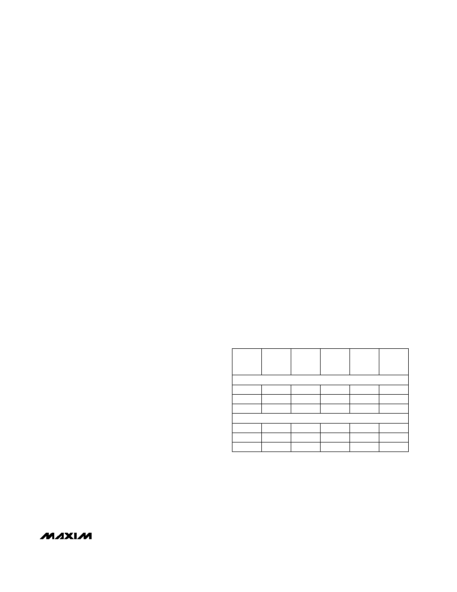
Table 1 shows optimal values for the feedback resistor
(RF) and gain-setting resistor (RG) for the MAX4223–
MAX4228. Note that the MAX4224/MAX4227/MAX4228
offer superior AC performance for all gains except unity
gain (0dB). These values provide optimal AC response
using surface-mount resistors and good layout tech-
niques. Maxim’s high-speed amplifier evaluation kits
provide practical examples of such layout techniques.
Stray capacitance at IN- causes feedback resistor
decoupling and produces peaking in the frequency-
response curve. Keep the capacitance at IN- as low as
possible by using surface-mount resistors and by
avoiding the use of a ground plane beneath or beside
these resistors and the IN- pin. Some capacitance is
unavoidable; if necessary, its effects can be counter-
acted by adjusting RF. Use 1% resistors to maintain
consistency over a wide range of production lots.
Table 1. Optimal Feedback Resistor
Networks
MAX4223/MAX4225/MAX4226
2
6
200
380
115
GAIN
(dB)
RG
(
)
RF
(
)
0.1dB
BW
(MHz)
GAIN
(V/V)
-3dB
BW
(MHz)
5
14
100
25
235
65
2
6
470
600
200
5
14
240
62
400
90
10
20
130
15
195
35
MAX4224/MAX4227/MAX4228
*
For the MAX4223EUT, this optimal value is 470
.
1
0
560*
Open
1000
300
相关PDF资料 |
PDF描述 |
|---|---|
| MAX4234AUD/V+ | IC OPAMP I/O R-R 10MHZ 14-TSSOP |
| MAX4236AEUA+T | IC OP AMP R-R 8-UMAX |
| MAX4239AUT#TG16 | IC AMP LN HIGH PREC SOT23-6 |
| MAX4244ESD+T | IC OP AMP BTR 14-SOIC |
| MAX4247AUB+T | IC OP AMP LOW POWER 10-UMAX |
相关代理商/技术参数 |
参数描述 |
|---|---|
| MAX4228ESD+ | 功能描述:高速运算放大器 1GHz Current Feedback Amp RoHS:否 制造商:Texas Instruments 通道数量:1 电压增益 dB:116 dB 输入补偿电压:0.5 mV 转换速度:55 V/us 工作电源电压:36 V 电源电流:7.5 mA 最大工作温度:+ 85 C 安装风格:SMD/SMT 封装 / 箱体:SOIC-8 封装:Tube |
| MAX4228ESD+T | 功能描述:高速运算放大器 1GHz Current Feedback Amp RoHS:否 制造商:Texas Instruments 通道数量:1 电压增益 dB:116 dB 输入补偿电压:0.5 mV 转换速度:55 V/us 工作电源电压:36 V 电源电流:7.5 mA 最大工作温度:+ 85 C 安装风格:SMD/SMT 封装 / 箱体:SOIC-8 封装:Tube |
| MAX4228ESD-T | 功能描述:高速运算放大器 RoHS:否 制造商:Texas Instruments 通道数量:1 电压增益 dB:116 dB 输入补偿电压:0.5 mV 转换速度:55 V/us 工作电源电压:36 V 电源电流:7.5 mA 最大工作温度:+ 85 C 安装风格:SMD/SMT 封装 / 箱体:SOIC-8 封装:Tube |
| MAX4228EUB | 功能描述:高速运算放大器 RoHS:否 制造商:Texas Instruments 通道数量:1 电压增益 dB:116 dB 输入补偿电压:0.5 mV 转换速度:55 V/us 工作电源电压:36 V 电源电流:7.5 mA 最大工作温度:+ 85 C 安装风格:SMD/SMT 封装 / 箱体:SOIC-8 封装:Tube |
| MAX4228EUB+ | 功能描述:高速运算放大器 1GHz Current Feedback Amp RoHS:否 制造商:Texas Instruments 通道数量:1 电压增益 dB:116 dB 输入补偿电压:0.5 mV 转换速度:55 V/us 工作电源电压:36 V 电源电流:7.5 mA 最大工作温度:+ 85 C 安装风格:SMD/SMT 封装 / 箱体:SOIC-8 封装:Tube |
发布紧急采购,3分钟左右您将得到回复。