- 您现在的位置:买卖IC网 > PDF目录2088 > MAX4295EEE+ (Maxim Integrated Products)IC AMP AUDIO PWR 2W MONO 16QSOP PDF资料下载
参数资料
| 型号: | MAX4295EEE+ |
| 厂商: | Maxim Integrated Products |
| 文件页数: | 4/15页 |
| 文件大小: | 0K |
| 描述: | IC AMP AUDIO PWR 2W MONO 16QSOP |
| 产品培训模块: | Lead (SnPb) Finish for COTS Obsolescence Mitigation Program |
| 标准包装: | 100 |
| 类型: | D 类 |
| 输出类型: | 1-通道(单声道) |
| 在某负载时最大输出功率 x 通道数量: | 2W x 1 @ 4 欧姆 |
| 电源电压: | 2.7 V ~ 5.5 V |
| 特点: | 消除爆音,短路保护和热保护,关闭 |
| 安装类型: | 表面贴装 |
| 供应商设备封装: | 16-QSOP |
| 封装/外壳: | 16-SSOP(0.154",3.90mm 宽) |
| 包装: | 管件 |
MAX4295
Mono, 2W, Switch-Mode (Class D)
Audio Power Amplifier
12
______________________________________________________________________________________
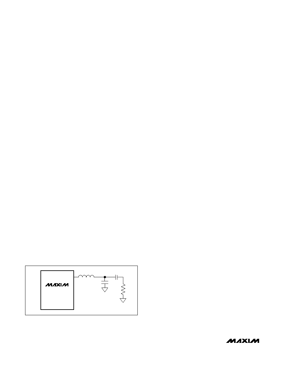
Cc
RL
C1
OUT+
OUT-
16
MAX4295
L1a
1
Figure 5. MAX4295 Single-Ended Configuration
Filter Components
The inductor current rating should be higher than the
peak current for a given output power requirement and
should have relatively constant inductance over tem-
perature and frequency. Typically, an open-core induc-
tor is desirable since these types of inductors are more
linear. Toroidal inductors without an air gap are not rec-
ommended. Q-shielded inductors may be required if
the amplifier is placed in an EMI-sensitive system. The
series resistance of the inductors will reduce the atten-
uation of the switching frequency and reduce efficiency
due to the ripple current in the inductor.
The capacitors should have a voltage rating 2 to 3
times the maximum expected RMS voltage—allowing
for high peak voltages and transient spikes—and be
stable over temperature. Good quality capacitors with
low equivalent series resistance (ESR) and equivalent
series inductance (ESL) are necessary to achieve opti-
mum performance. Low-ESR capacitors will decrease
power dissipation. High ESL will shift the cutoff frequen-
cy, and high ESR will reduce filter rolloff.
Bridge-Tied Load/Single-Ended
Configuration
The MAX4295 can be used as either a BTL or single-
ended configured amplifier. The BTL configuration offers
several advantages over a single-ended configuration.
By driving the load differentially, the output voltage swing
is doubled and the output power is quadrupled in com-
parison to a single-ended configuration. Because the dif-
ferential outputs are biased at half supply, there is no DC
voltage across the load, eliminating the need for large
DC-blocking capacitors at the output.
The MAX4295 can be configured as a single-ended
amplifier. In such a case, the load must be capacitively
coupled to the filter to block the half-supply DC voltage
from the load. The unused output pin must also be left
open (Figure 5). Do not connect the unused output pin
to ground.
Total Harmonic Distortion
The MAX4295 exhibits typical THD+N of <1% for input
frequencies <10kHz. The PWM frequency affects THD
performance. THD can be reduced by limiting the input
bandwidth through the input highpass filter, choosing
the lowest fOSC possible, and carefully selecting the
output filter and its components.
Bypassing and Layout Considerations
Distortion caused by supply ripple due to H-bridge
switching can be reduced through proper bypassing of
PVCC. For optimal performance, a 330F, low-ESR
POSCAP capacitor to PGND and a 1F ceramic capac-
itor to GND at each PVCC input is suggested. Place the
1F capacitor close to the PVCC pin. Bypass VCC with
a 10F capacitor in parallel with a 1F capacitor to
GND. Ceramic capacitors are recommended due to
their low ESR.
Good PC board layout techniques optimize perfor-
mance by decreasing the amount of stray capacitance
at the amplifier’s inputs and outputs. To decrease stray
capacitance, minimize trace lengths by placing exter-
nal components as close as possible to the amplifier.
Surface-mount components are recommended.
The MAX4295 requires two separate ground planes to
prevent switching noise from the MOSFETs in the H-
bridge from coupling into the rest of the circuit. PGND,
the power ground, is utilized by the H-bridge and any
external output components, while GND is used by the
rest of the circuit. Connect the PGND and GND planes
at only one point, as close to the power supply as pos-
sible. Any external components associated with the
output of the MAX4295 must be connected to the
PGND plane where applicable. Use the Typical
Operating Circuit diagram as a reference. Refer to the
evaluation kit manual for suggested component values,
component suppliers, and layout.
相关PDF资料 |
PDF描述 |
|---|---|
| MAX4299EWP+T | IC DVR/STEREO W/MIC/REG 20-SOIC |
| MAX4365ETA+T | IC AMP AUDIO PWR 1W MONO 8TDFN |
| MAX4368ETA+T | IC AMP AUDIO PWR .33W MONO 8TDFN |
| MAX4374HEUB+T | IC AMP CURRENT SENSE 10-UMAX |
| MAX4386EESD+T | IC OP AMP R-R SNGL 14-SOIC |
相关代理商/技术参数 |
参数描述 |
|---|---|
| MAX4295EEE+ | 功能描述:音频放大器 Mono 2W Switch Mode (Class D) RoHS:否 制造商:STMicroelectronics 产品:General Purpose Audio Amplifiers 输出类型:Digital 输出功率: THD + 噪声: 工作电源电压:3.3 V 电源电流: 最大功率耗散: 最大工作温度: 安装风格:SMD/SMT 封装 / 箱体:TQFP-64 封装:Reel |
| MAX4295EEE+T | 功能描述:音频放大器 Mono 2W Switch Mode (Class D) RoHS:否 制造商:STMicroelectronics 产品:General Purpose Audio Amplifiers 输出类型:Digital 输出功率: THD + 噪声: 工作电源电压:3.3 V 电源电流: 最大功率耗散: 最大工作温度: 安装风格:SMD/SMT 封装 / 箱体:TQFP-64 封装:Reel |
| MAX4295EEE-T | 功能描述:音频放大器 RoHS:否 制造商:STMicroelectronics 产品:General Purpose Audio Amplifiers 输出类型:Digital 输出功率: THD + 噪声: 工作电源电压:3.3 V 电源电流: 最大功率耗散: 最大工作温度: 安装风格:SMD/SMT 封装 / 箱体:TQFP-64 封装:Reel |
| MAX4295ESE | 功能描述:音频放大器 RoHS:否 制造商:STMicroelectronics 产品:General Purpose Audio Amplifiers 输出类型:Digital 输出功率: THD + 噪声: 工作电源电压:3.3 V 电源电流: 最大功率耗散: 最大工作温度: 安装风格:SMD/SMT 封装 / 箱体:TQFP-64 封装:Reel |
| MAX4295ESE+ | 功能描述:音频放大器 Mono 2W Switch Mode (Class D) RoHS:否 制造商:STMicroelectronics 产品:General Purpose Audio Amplifiers 输出类型:Digital 输出功率: THD + 噪声: 工作电源电压:3.3 V 电源电流: 最大功率耗散: 最大工作温度: 安装风格:SMD/SMT 封装 / 箱体:TQFP-64 封装:Reel |
发布紧急采购,3分钟左右您将得到回复。