- 您现在的位置:买卖IC网 > PDF目录2157 > MAX4305ESA+ (Maxim Integrated Products)IC OP AMP LOW NOISE 8-SOIC PDF资料下载
参数资料
| 型号: | MAX4305ESA+ |
| 厂商: | Maxim Integrated Products |
| 文件页数: | 12/12页 |
| 文件大小: | 0K |
| 描述: | IC OP AMP LOW NOISE 8-SOIC |
| 产品培训模块: | Lead (SnPb) Finish for COTS Obsolescence Mitigation Program |
| 标准包装: | 100 |
| 放大器类型: | 电压反馈 |
| 电路数: | 1 |
| 转换速率: | 1400 V/µs |
| -3db带宽: | 340MHz |
| 电流 - 输入偏压: | 32µA |
| 电压 - 输入偏移: | 1000µV |
| 电流 - 电源: | 20mA |
| 电流 - 输出 / 通道: | 70mA |
| 电压 - 电源,单路/双路(±): | ±3.5 V ~ 5.5 V |
| 工作温度: | -40°C ~ 85°C |
| 安装类型: | 表面贴装 |
| 封装/外壳: | 8-SOIC(0.154",3.90mm 宽) |
| 供应商设备封装: | 8-SOIC |
| 包装: | 管件 |
| 产品目录页面: | 1389 (CN2011-ZH PDF) |
_______________Detailed Description
The MAX4104/MAX4105/MAX4304/MAX4305 are ultra-
high-speed, low-noise amplifiers featuring -3dB band-
widths up to 880MHz, 0.1dB gain flatness up to
100MHz, and low differential gain and phase errors of
0.01% and 0.01°, respectively. These devices operate
on dual power supplies ranging from ±3.5V to ±5.5V
and require only 20mA of supply current.
The MAX4104/MAX4304/MAX4105/MAX4305 are opti-
mized for minimum closed-loop gains of +1V/V, +2V/V,
+5V/V and +10V/V (respectively) with corresponding
-3dB bandwidths of 880MHz, 730MHz, 430MHz, and
350MHz. Each device in this family features a low input
voltage noise density of only 2.1nV/
√Hz (at 1MHz), an
output current drive of ±70mA, and spurious-free
dynamic range as low as -88dBc (5MHz, RL = 100).
___________Applications Information
Layout and Power-Supply Bypassing
The MAX4104/MAX4105/MAX4304/MAX4305 have an
extremely high bandwidth, and consequently require
careful board layout, including the possible use of
constant-impedance microstrip or stripline techniques.
To realize the full AC performance of these high-speed
amplifiers, pay careful attention to power-supply
bypassing and board layout. The PC board should
have at least two layers: a signal and power layer on
one side, and a large, low-impedance ground plane on
the other side. The ground plane should be as free of
voids as possible. With multilayer boards, locate the
ground plane on a layer that incorporates no signal or
power traces.
Regardless of whether or not a constant-impedance
board is used, it is best to observe the following guide-
lines when designing the board:
1) Do not use wire-wrapped boards (they are much too
inductive) or breadboards (they are much too
capacitive).
2) Do not use IC sockets. IC sockets increase reac-
tances.
3) Keep signal lines as short and straight as possible.
Do not make 90° turns; round all corners.
4) Observe high-frequency bypassing techniques to
maintain the amplifier’s accuracy and stability.
5) Bear in mind that, in general, surface-mount compo-
nents have shorter bodies and lower parasitic reac-
tance, resulting in greatly improved high-frequency
performance over through-hole components.
The bypass capacitors should include 1nF and 0.1F
ceramic surface-mount capacitors between each sup-
ply pin and the ground plane, located as close to the
package as possible. Optionally, place a 10F tantalum
capacitor at the power supply pins’ point of entry to the
PC board to ensure the integrity of incoming supplies.
The power-supply trace should lead directly from the
tantalum capacitor to the VCC and VEE pins. To mini-
mize parasitic inductance, keep PC traces short and
use surface-mount components.
Input termination resistors and output back-termination
resistors, if used, should be surface-mount types, and
should be placed as close to the IC pins as possible.
DC and Noise Errors
The MAX4104/MAX4105/MAX4304/MAX4305 output
offset voltage, VOUT (Figure 1), can be calculated with
the following equation:
VOUT = [VOS + (IB+ x RS) + (IB- x (RF
|| RG))] [1 + RF / RG]
where:
VOS = input offset voltage (in volts)
1 + RF/RG = amplifier closed-loop gain (dimensionless)
IB+ = noninverting input bias current (in amps)
IB- = inverting input bias current (in amps)
RG = gain-setting resistor (in ohms)
RF = feedback resistor (in ohms)
RS = source resistor at noninverting input (in ohms)
The following equation represents output noise density:
e
1
R
i x R
R
e
n(OUT)
F
G
n
S
2
n
F
G
2
n
2
||
=
+
(
) + (
)
+
MAX4104/MAX4105/MAX4304/MAX4305
740MHz, Low-Noise, Low-Distortion
Op Amps in SOT23-5
_______________________________________________________________________________________
9
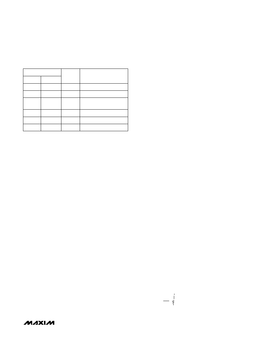
_____________________Pin Description
SOT23-5
SO
OUT
VCC
VEE
IN+
IN-
N.C.
NAME
Amplifier Output
6
1
Positive Power Supply
7
5
Negative Power Supply
4
2
Amplifier Noninverting
Input
3
Amplifier Inverting Input
2
4
Not internally connected.
1, 5, 8
—
FUNCTION
PIN
相关PDF资料 |
PDF描述 |
|---|---|
| MAX430EPA | IC OPAMP +/-15V CHOP/STAB 8-DIP |
| MAX4321EUK-T | IC OPAMP 5MHZ R-TO-R I/O SOT23-5 |
| MAX4329ESD+T | IC OP AMP R-R I/O LP 14-SOIC |
| MAX4334ESD+T | IC OP AMP R-R I/O LP 14-SOIC |
| MAX4337EKA+T | IC OP AMP R-R I/O W/SD SOT23-8 |
相关代理商/技术参数 |
参数描述 |
|---|---|
| MAX4305ESA+ | 功能描述:运算放大器 - 运放 740MHz Low-Noise ow-Distortion RoHS:否 制造商:STMicroelectronics 通道数量:4 共模抑制比(最小值):63 dB 输入补偿电压:1 mV 输入偏流(最大值):10 pA 工作电源电压:2.7 V to 5.5 V 安装风格:SMD/SMT 封装 / 箱体:QFN-16 转换速度:0.89 V/us 关闭:No 输出电流:55 mA 最大工作温度:+ 125 C 封装:Reel |
| MAX4305ESA+T | 功能描述:运算放大器 - 运放 740MHz Low-Noise ow-Distortion RoHS:否 制造商:STMicroelectronics 通道数量:4 共模抑制比(最小值):63 dB 输入补偿电压:1 mV 输入偏流(最大值):10 pA 工作电源电压:2.7 V to 5.5 V 安装风格:SMD/SMT 封装 / 箱体:QFN-16 转换速度:0.89 V/us 关闭:No 输出电流:55 mA 最大工作温度:+ 125 C 封装:Reel |
| MAX4305ESA-T | 功能描述:运算放大器 - 运放 RoHS:否 制造商:STMicroelectronics 通道数量:4 共模抑制比(最小值):63 dB 输入补偿电压:1 mV 输入偏流(最大值):10 pA 工作电源电压:2.7 V to 5.5 V 安装风格:SMD/SMT 封装 / 箱体:QFN-16 转换速度:0.89 V/us 关闭:No 输出电流:55 mA 最大工作温度:+ 125 C 封装:Reel |
| MAX4305EUK | 制造商:Maxim Integrated Products 功能描述:- Rail/Tube |
| MAX4305EUK+ | 制造商:Maxim Integrated Products 功能描述:OP AMP SGL GP 5.5V 5PIN SOT-23 - Rail/Tube |
发布紧急采购,3分钟左右您将得到回复。