- 您现在的位置:买卖IC网 > PDF目录11317 > MAX4359EWG+ (Maxim Integrated Products)IC VIDEO CROSSPOINT SWIT 24SOIC PDF资料下载
参数资料
| 型号: | MAX4359EWG+ |
| 厂商: | Maxim Integrated Products |
| 文件页数: | 16/17页 |
| 文件大小: | 0K |
| 描述: | IC VIDEO CROSSPOINT SWIT 24SOIC |
| 产品培训模块: | Lead (SnPb) Finish for COTS Obsolescence Mitigation Program |
| 标准包装: | 30 |
| 功能: | 视频交叉点开关 |
| 电路: | 1 x 4:4 |
| 电压电源: | 双电源 |
| 电压 - 电源,单路/双路(±): | ±4.5 V ~ 5.5 V |
| 工作温度: | -40°C ~ 85°C |
| 安装类型: | 表面贴装 |
| 封装/外壳: | 24-SOIC(0.295",7.50mm 宽) |
| 供应商设备封装: | 24-SOIC W |
| 包装: | 管件 |
MAX4359/MAX4360/MAX4456
Low-Cost 4x4, 8x4, 8x8
Video Crosspoint Switches
8
_______________________________________________________________________________________
32-Bit Serial-Interface Mode (MAX4456)
In serial mode (SER/PAR = VCC), all first-rank registers
are loaded with data, making it unnecessary to specify
an output address (A2, A1, A0). The input data format
is D3–D0, starting with OUT0 and ending with OUT7 for
32 total bits. Only codes 0000 through 1010 are valid.
Code 1010 disables a buffer, while code 1001 enables
it. After data is shifted into the 32-bit first-rank register,
it is transferred to the second rank by LATCH (Table 2),
which updates the switches.
Typical Application
Figure 2 shows a typical application of the MAX4456
(PDIP) with the MAX4395 quad, operational amplifiers
at the outputs to drive 75
loads. This application
shows the MAX4456 digital-switch control interface set
up in the 7-bit parallel mode. The MAX4456 uses seven
data lines and two control lines (WR and LATCH). Two
additional lines may be needed to control CE and
LOAD when using multiple MAX4456s.
The input/output information is presented to the chip at
A2, A1, A0, and D3–D0 by a parallel printer port. The
data is stored in the 1st-rank registers on the rising
edge of WR. When the LATCH line goes high, the
switch configuration is loaded into the 2nd-rank regis-
ters, and all eight outputs enter the new configuration at
the same time. Each 7-bit word updates only one out-
put buffer at a time. If several buffers are to be updat-
ed, the data is individually loaded into the 1st-rank reg-
isters. Then, a single LATCH pulse is used to reconfig-
ure all channels simultaneously.
The short BASIC program in Figure 3 loads programming
data into the MAX4456 from any IBM PC or compatible. It
uses the computer’s “LPT1” output to interface to the cir-
cuit, then automatically finds the address for LPT1 and
displays a table of valid input values to be used. The pro-
gram does not keep track of previous commands, but it
does display the last data sent to LPT1, which is written
and latched with each transmission. A similar application
is possible with the MAX4359/MAX4360.
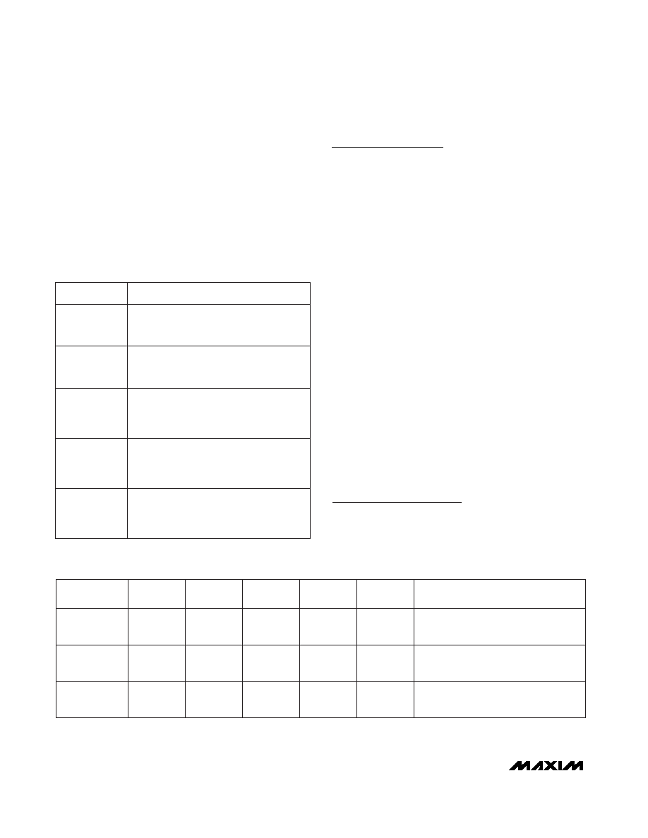
SERIAL /
PARALLEL
D3
H
X
L
H
L
(A2), A1,
A0
X
Output
Buffer
Address
Output
Buffer
Address
D1
Serial
Output
Parallel
Input
Parallel
Input
D2
X
Parallel
Input
Parallel
Input
D0
Serial Input
Parallel
Input
Parallel
Input
COMMENT
Serial Mode
Parallel Mode,
D0–D2 = Control Code
Parallel Mode,
D0–D2 = Input Address
L
Table 3. Input/Output Line Configurations
X = Don’t care, H = 5V, L = 0V
( ) are for MAX4456 only.
Table 2. Serial-Interface Mode Functions
D3–D0
FUNCTION
0000 to 0111
Connect the selected buffer to the input
channel selected by D3–D0. Note that 0100
through 0111 are not valid for the MAX4359.
1000
Connect the input of the selected buffer to
GND. Note: If the buffer output remains
on, its input is its offset voltage.
1001
Turn on the selected buffer and connect
its input to GND. Use this code to turn on
buffers after power is applied. The default
power-up state is all buffers disabled.
1010
Shut off the selected buffer at the speci-
fied channel, and erase data stored in the
2nd rank of registers. The 2nd rank now
holds the command word 1010.
1011 to 1111
Do not use these codes in the serial-inter-
face mode. They inhibit the latching of the
2nd-rank registers, which prevents proper
data loading.
Chip Information
MAX4359 TRANSISTOR COUNT: 2372
MAX4360 TRANSISTOR COUNT: 2372
MAX4456 TRANSISTOR COUNT: 3820
相关PDF资料 |
PDF描述 |
|---|---|
| PIC18F6622T-I/PT | IC PIC MCU FLASH 32KX16 64TQFP |
| MAX329CWE+ | IC MULTIPLEXER DUAL 4X1 16SOIC |
| PIC16LF77T-I/PT | IC MCU FLASH 8KX14 A/D 44TQFP |
| MAX337EWI+ | IC MULTIPLEXER DUAL 8X1 28SOIC |
| PIC16F876T-20I/SO | IC MCU FLASH 8KX14 EE 28SOIC |
相关代理商/技术参数 |
参数描述 |
|---|---|
| MAX4359EWG+ | 功能描述:模拟和数字交叉点 IC 4x4 Video Crosspoint Switch RoHS:否 制造商:Micrel 配置:2 x 2 封装 / 箱体:MLF-16 数据速率:10.7 Gbps 输入电平:CML, LVDS, LVPECL 输出电平:CML 电源电压-最大:3.6 V 电源电压-最小:2.375 V 最大工作温度:+ 85 C 最小工作温度:- 40 C 产品:Digital Crosspoint 封装:Tube |
| MAX4359EWG+T | 功能描述:视频开关 IC 4x4 Video Crosspoint Switch RoHS:否 制造商:Texas Instruments 开关数量:4 开启电阻(最大值):12 Ohms 传播延迟时间: 开启时间(最大值): 关闭时间(最大值): 最大工作温度:+ 85 C 最小工作温度:- 40 C 封装 / 箱体:WQFN-42 封装:Reel |
| MAX4359EWG-T | 功能描述:模拟和数字交叉点 IC RoHS:否 制造商:Micrel 配置:2 x 2 封装 / 箱体:MLF-16 数据速率:10.7 Gbps 输入电平:CML, LVDS, LVPECL 输出电平:CML 电源电压-最大:3.6 V 电源电压-最小:2.375 V 最大工作温度:+ 85 C 最小工作温度:- 40 C 产品:Digital Crosspoint 封装:Tube |
| MAX435C/D | 功能描述:运算放大器 - 运放 RoHS:否 制造商:STMicroelectronics 通道数量:4 共模抑制比(最小值):63 dB 输入补偿电压:1 mV 输入偏流(最大值):10 pA 工作电源电压:2.7 V to 5.5 V 安装风格:SMD/SMT 封装 / 箱体:QFN-16 转换速度:0.89 V/us 关闭:No 输出电流:55 mA 最大工作温度:+ 125 C 封装:Reel |
| MAX435C/D DIE | 制造商:Maxim Integrated Products 功能描述: |
发布紧急采购,3分钟左右您将得到回复。